This is the log of building Shapeshifter - a one-off machine that is somehow both a full size vpin cabinet...
and also a sim-pit cockpit for flight simulators, racing games, and most of the sit-down arcade games.
(It's ambitious, but, I've already completed Mimic, so I think I may be able to do it.)
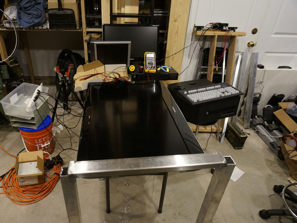
First mockup of parts, with a spare TV for a playfield, a spare LCD panel for the DMD, and a spare backglass panel.
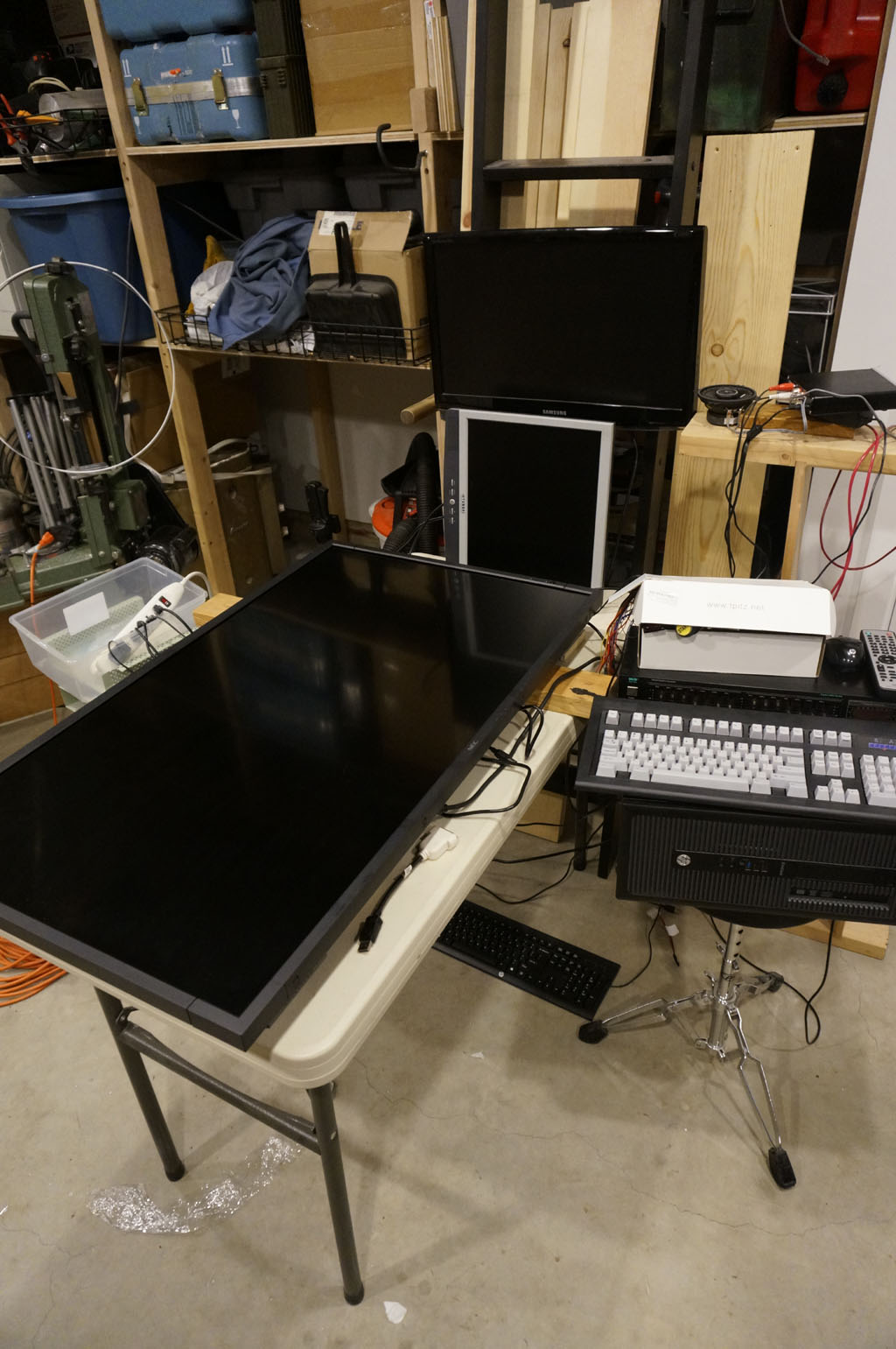
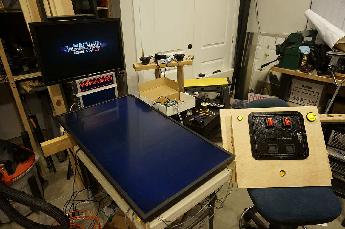
The spare TV's not cutting it. That black level is just... no.
This TV was very useful as far as providing the initial impetus and getting
things started, but - if I'm gonna do it, I'm going to design around a better panel.
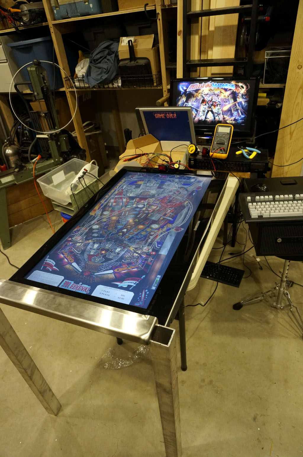
Here's a better playfield panel. Commercial signage panel, factory refurb, even 3/4" bezels on all sides.
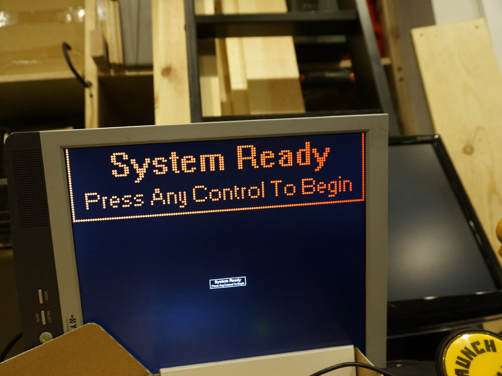
I'm writing my own front-end for it - for everything I need it to do, there's no choice. The machine will show status messages
on the DMD, which means they should look like a DMD. This is the first revision of my DMD simulator code.
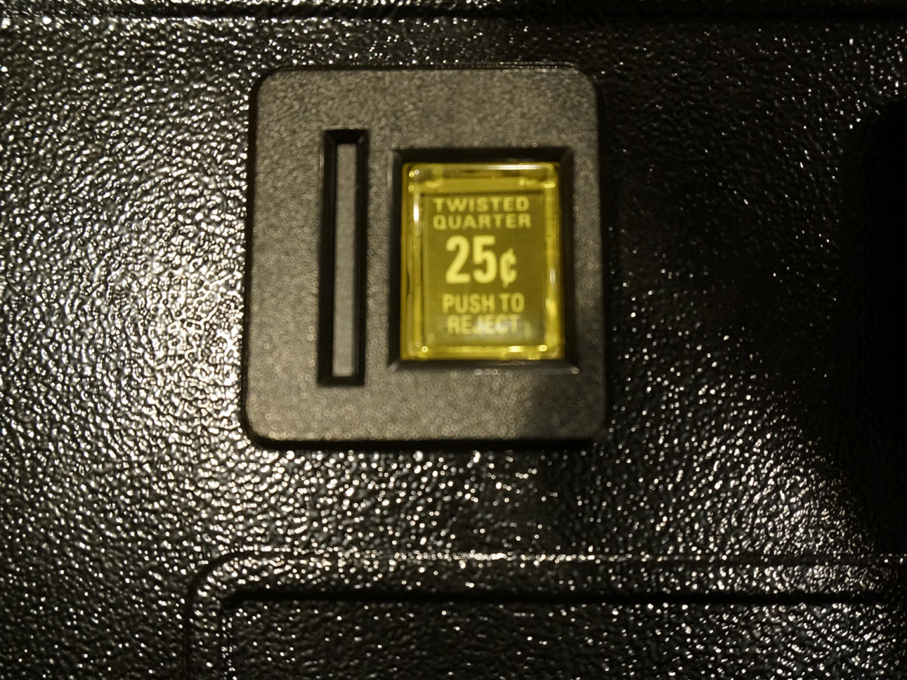
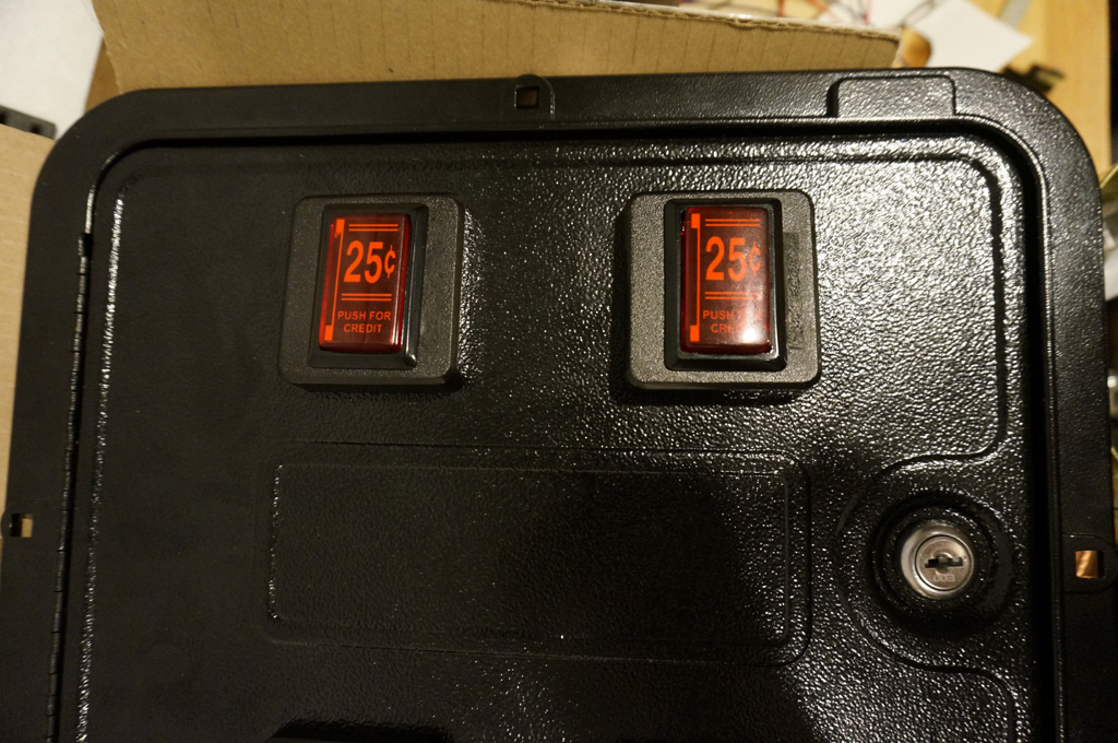
The coin door I got was neutered for MAME applications, with no coin mechs, and these yellow plungers were attached
to nothing. This is perfect, as I don't have the room inside the front box for any mechs anyway - but I prefer poker buttons
mounted in portrait, with red art to emulate the classic coin slot, as coin buttons.

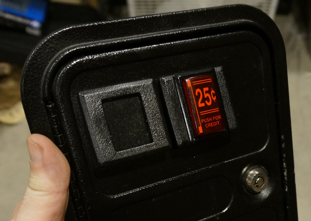
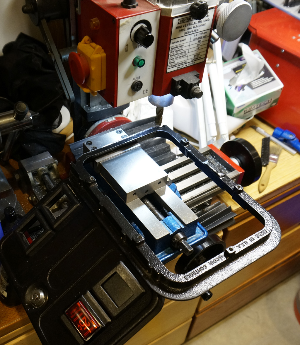
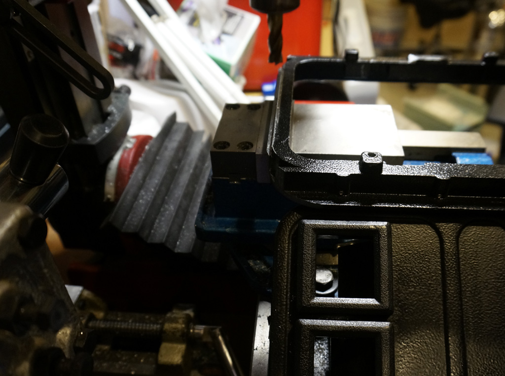
Removing material to make room for a poker button. It ends up involving significant excavation with a dremel tool.
(Part of the original plunger hole remains on the right - the combined cutouts were wider than a poker button is.)
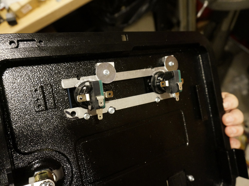
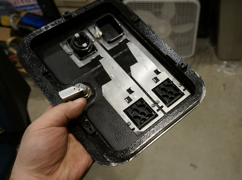
Some structure is necessary in the back of the coin door to give a poker button anything to attach to. This stuff will get cleaned up a little and painted black by the end.
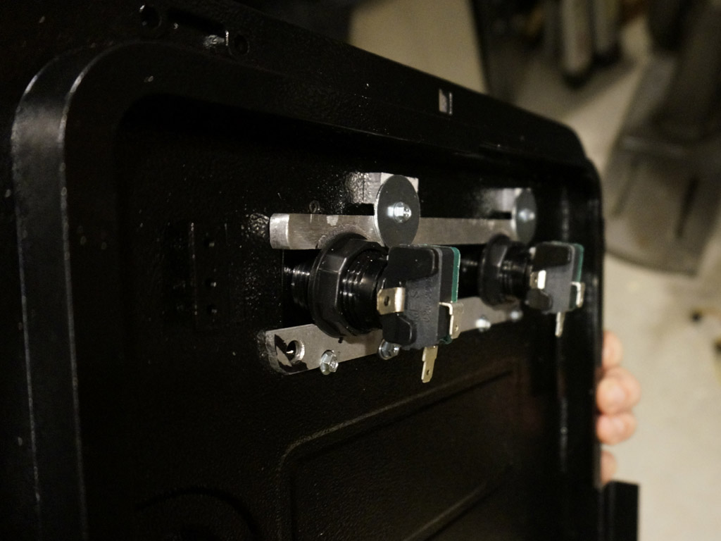
Here you can see the different thicknesses of shim top and bottom necessary to let a poker button keep the desired angle of the plastic bezel insert.
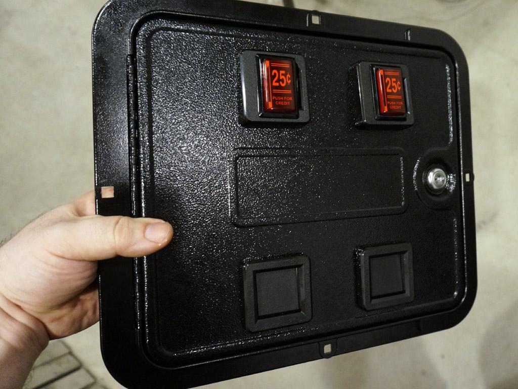
Got both coin buttons fit into the chutes. Still have to fix the residual slots on the right, or I'm certain
that someone will try to stuff a quarter in there...
Black epoxy putty fills the leftover gaps. Tried to reproduce the texture, but it's still slightly visible if the light's just right.
I may paint these to hide it further.
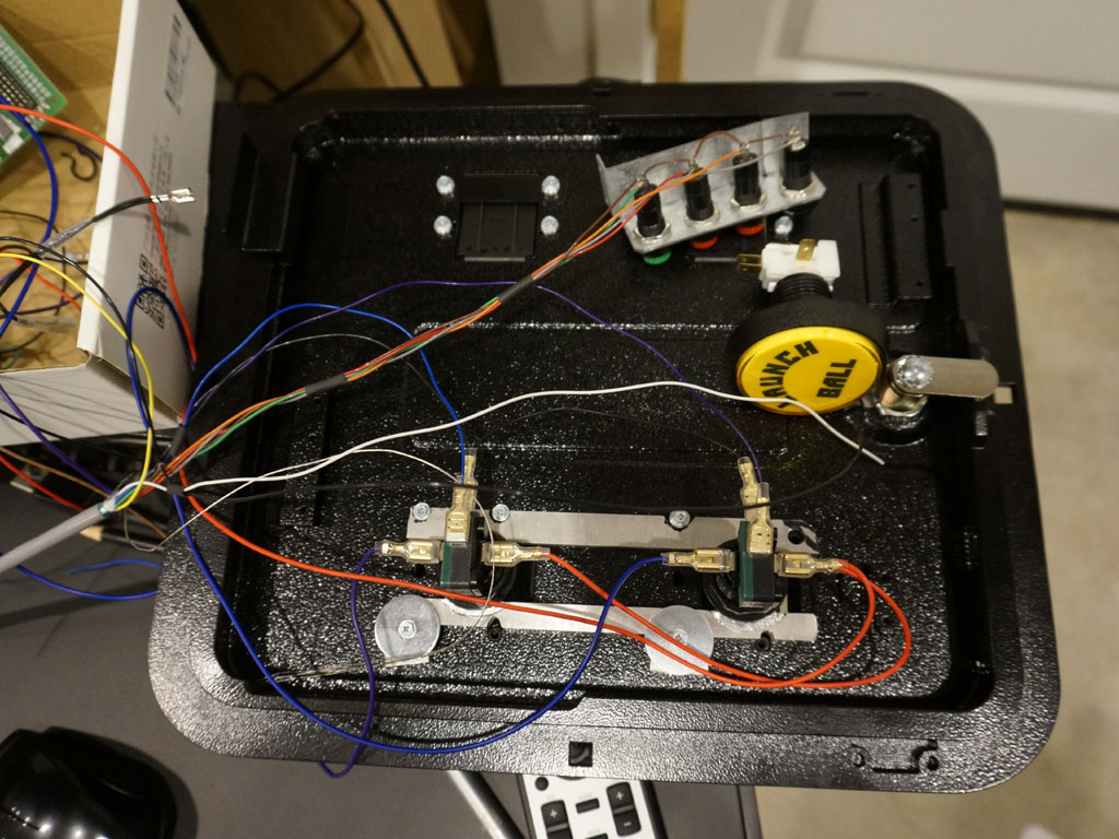
Starting to wire this thing up. There's a lot of wires.
Meanwhile, though, there's a whole second coin door, because the driving/flying cockpit side of this needs one, too.
A friend of mine gifted me an over-under, which is the perfect width, but far too tall... and the bottom door was kind of a basket case:
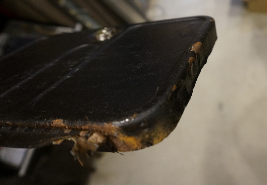
Pretty sure that's been pried open at least once. I don't feel bad about discarding this portion.
There's no two-person driving games that share one seat, so this one only needs a single coin button.
Which is good, because wow there's barely room to pull this button trick off, with these smaller chutes.
Having cut the bottom door off the siamesed frame, I now no longer have a mounting flange on the bottom edge of the coin door I'm keeping.
I don't need as much flange as the factory provides, but some would sure be nice.
So I milled a fresh one, using part of the thickness of the lower frame.
It's not a lot, but it's enough to cover any small imperfections in my mounting hole.
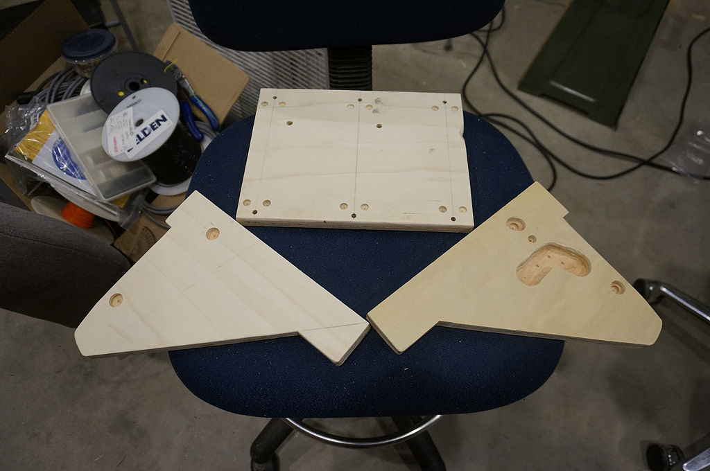
Next, time to start some cabinetry.
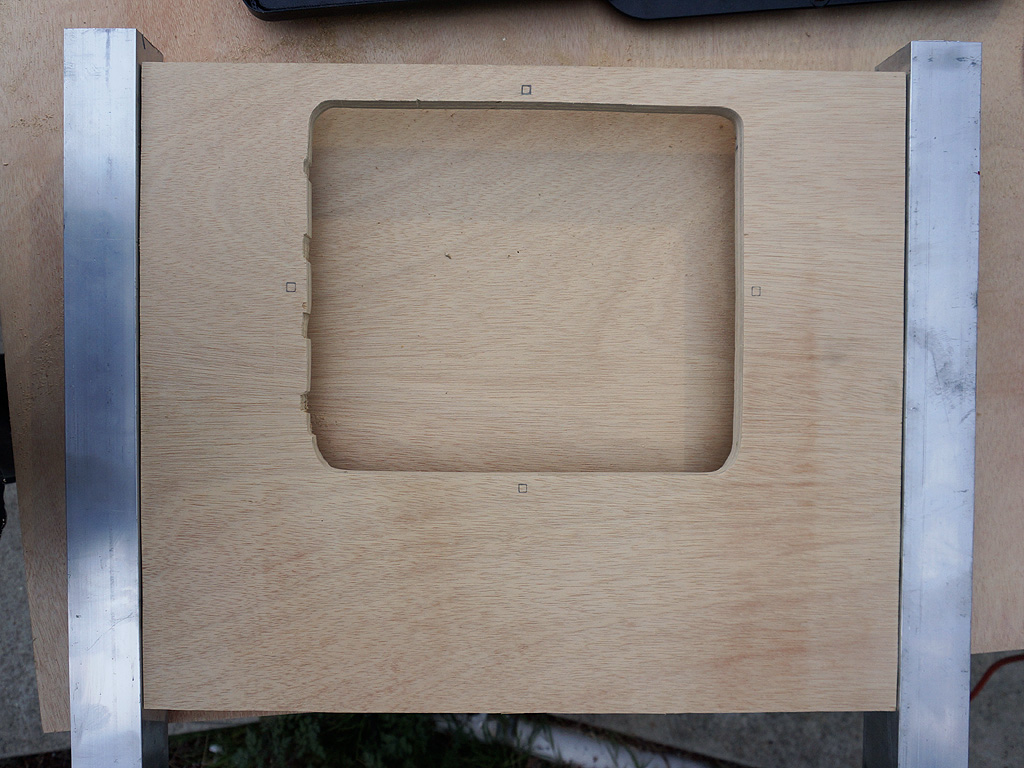
Here's the beginnings of the pinball front box. This is almost the correct coindoor cutout for the main door.
I screwed up the upper left corner, but not worse than will be hidden.
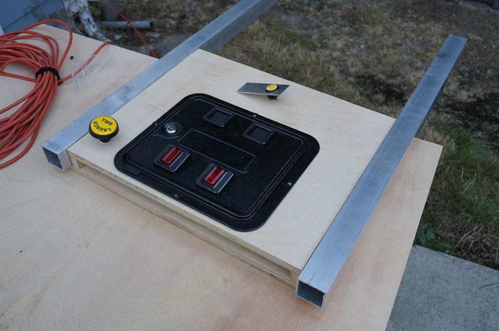
Coin door goes in like so. Some buttons go roughly here, and the legs stand 1/8" proud along the sides.
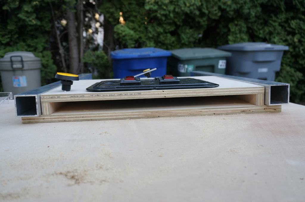
The front box is really, really, really shallow. 1 1/8" internal space, just enough for the buttons.
The coin door is mostly to provide me access to service any parts that
end up needing to be replaced.
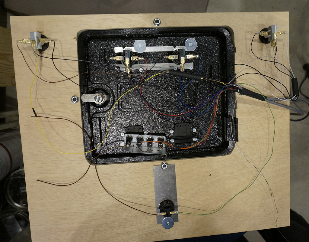
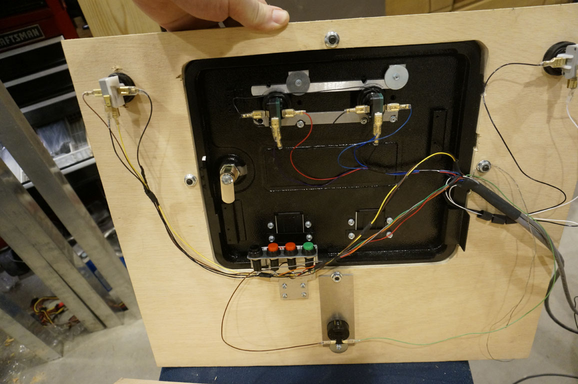
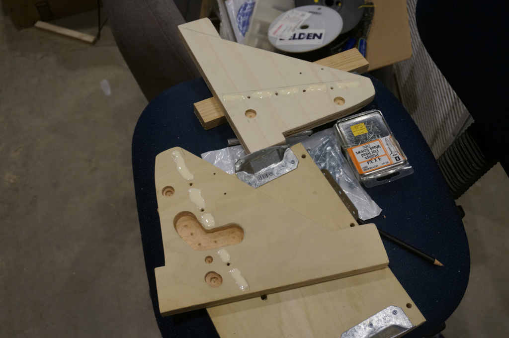
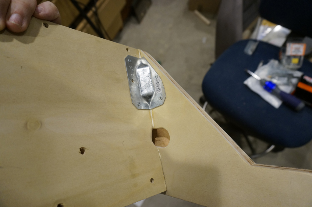
There's rather a lot of wiring to be done in the front box. Of interest here is the aluminum plate at the bottom - I wanted to be able to change out this
button without undoing and redoing threads in wood, so the plate has two
saddles that straddle hardware. Remove the upper nut off the coin door stud, and it tips out and comes out the top.
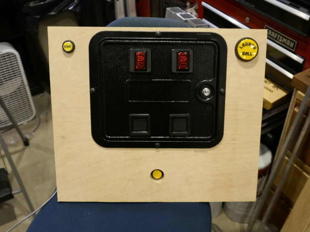
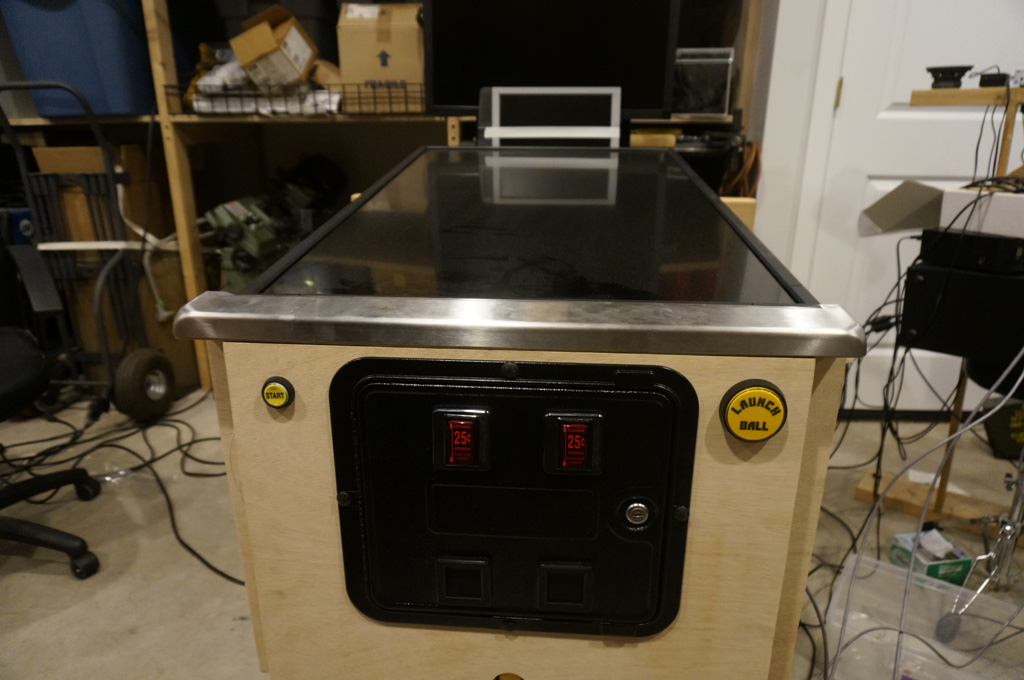
With all the guts in it, hey, this starts to look like the front of a pinball machine.
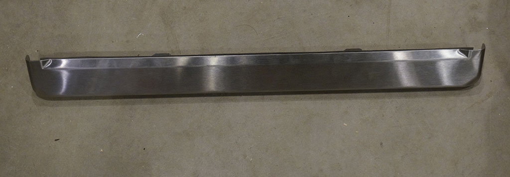
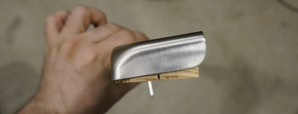
I didn't want to fabricate a lockdown bar. It's the main point of human contact when the machine is in pinball mode,
so having it feel right matters to me. This is a 25" wide Williams widebody bar, which I designed the rest of the
design to fit.
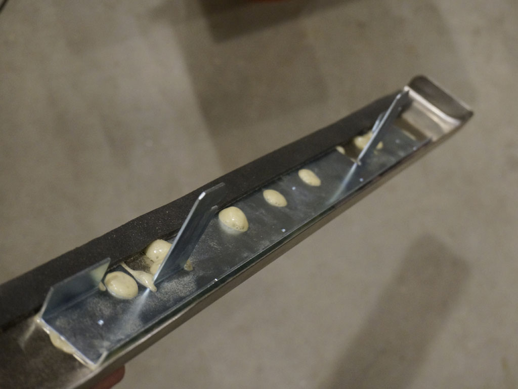
What I didn't initially know is that pinball lockdown bars provide an... interesting... interface to attach to.
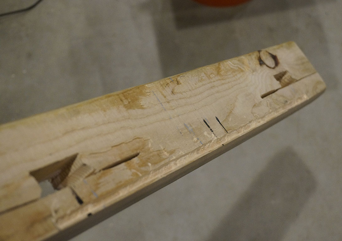
So, I grabbed a random 2x4 out of my shop and started carving. I wish I'd paid more attention, that knot is going to cause me trouble.
Inletting at about half completion; it should ultimately sink down until the foam gasket at the back compresses.
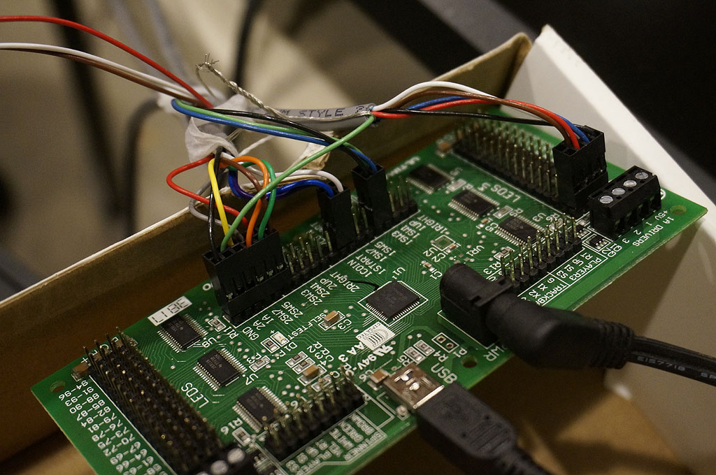
More wiring. This is the controller board that'll drive the lights, detect the switches, and also via relays control the transformation actuators and motors.

Ran into a big problem here. All this white light leakage from the LED - looks awful.
Doesn't remotely match the Launch Ball button.
Had to swaddle it in yellow translucent tape.

Much better.
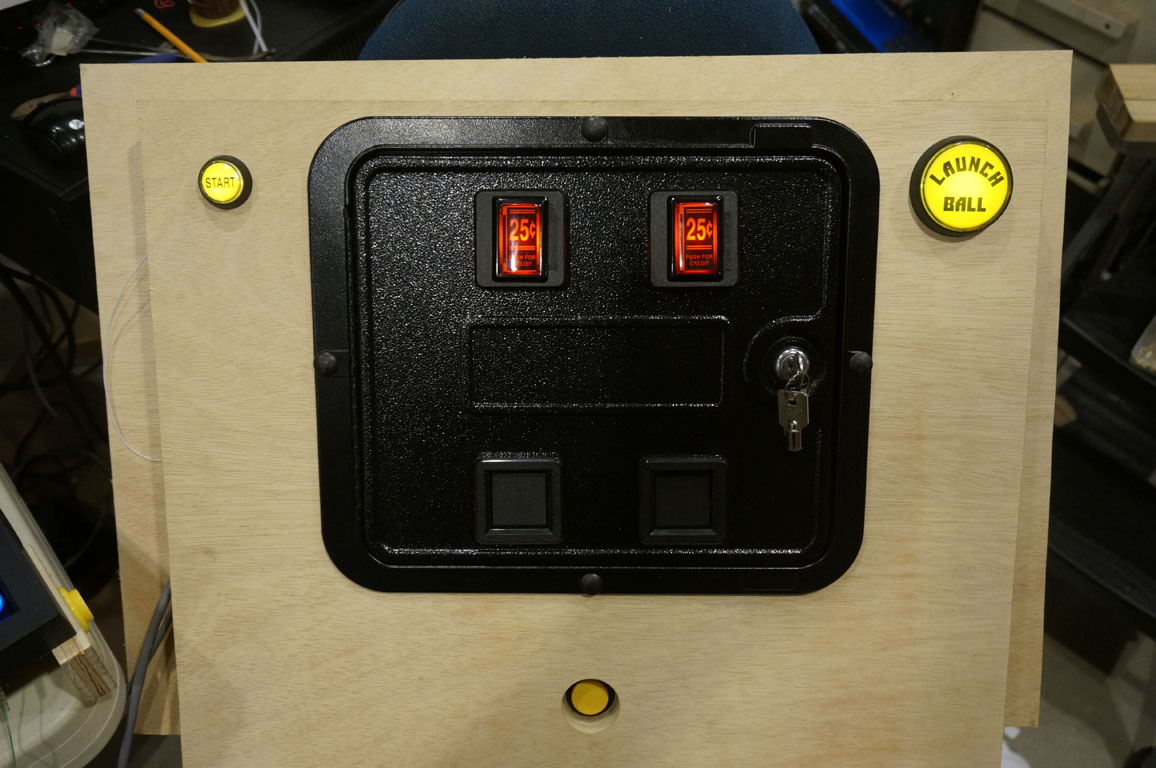
Now they match. Seeing everything lit up is gratifying.
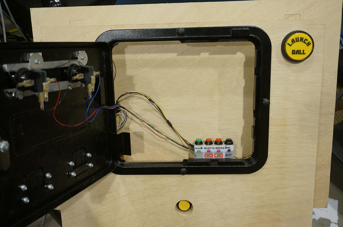
Here's a fun bit of simulation. I only have 1 1/8" of space in here, but real pinball machines have service buttons
attached to the back of the coin door. No room for that, but I can still put them behind the door like this.
Made a little bracket to hang them there.
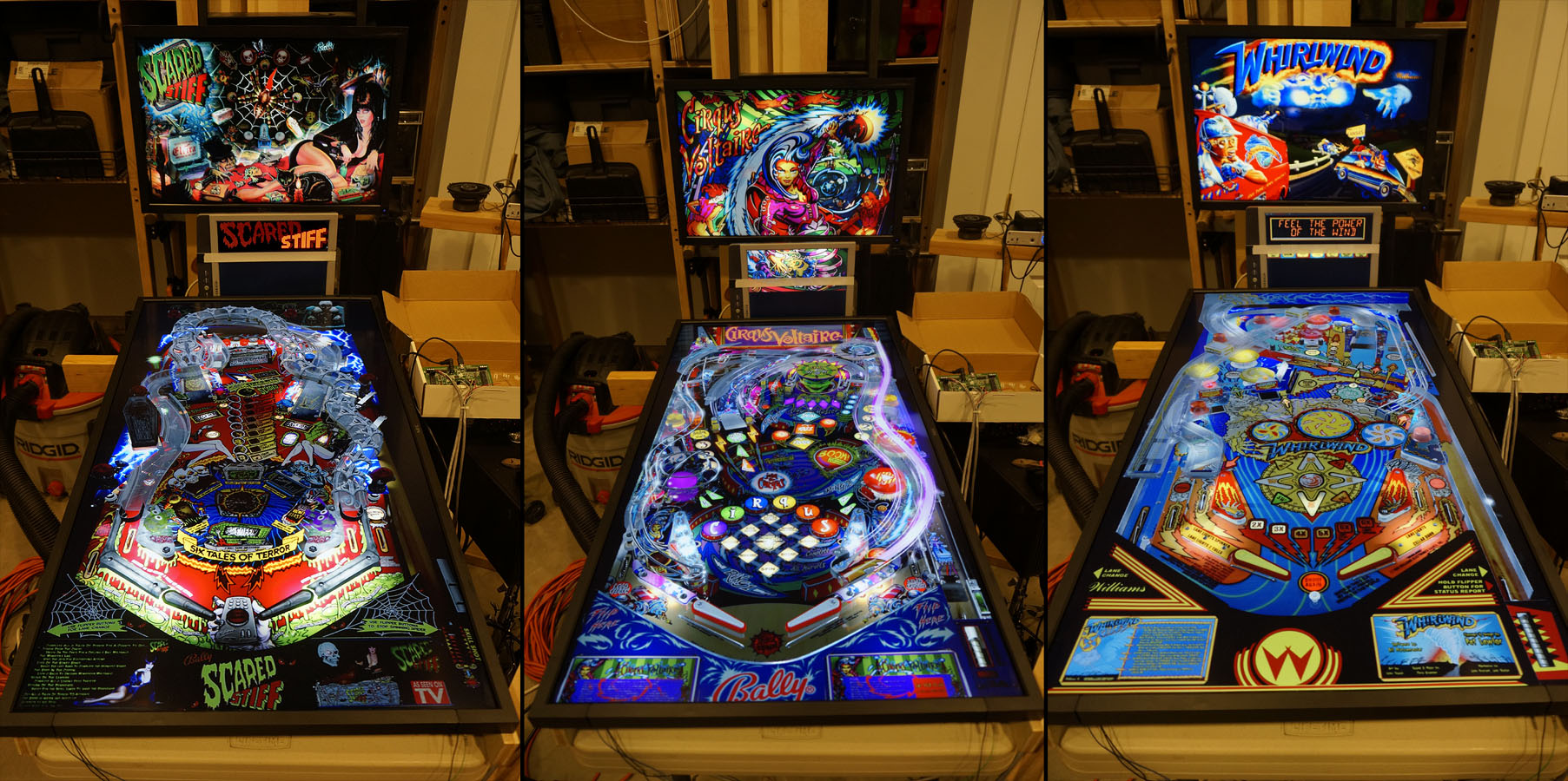
Here's my custom software running. In game selection mode, you use the flipper buttons to switch tables. The next few table logos are shown in each
direction, fading out. The logo for the machine goes on the fake dot matrix display.
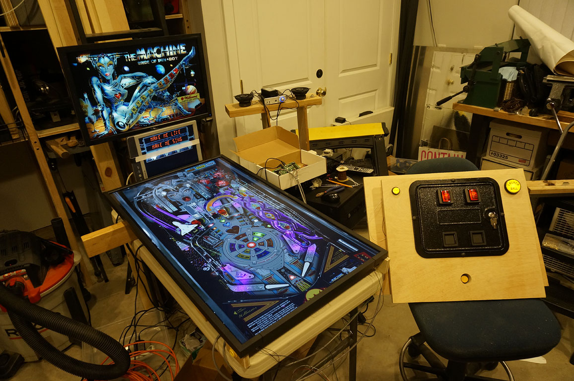
When you pick a table, it fires up like this.
These black levels on the new playfield panel - they'll do nicely.
Different games use the screens differently. By faking a DMD with a partially visible LCD panel, it can be
a DMD display, or part of the backglass, or a 15-segment plasma display.
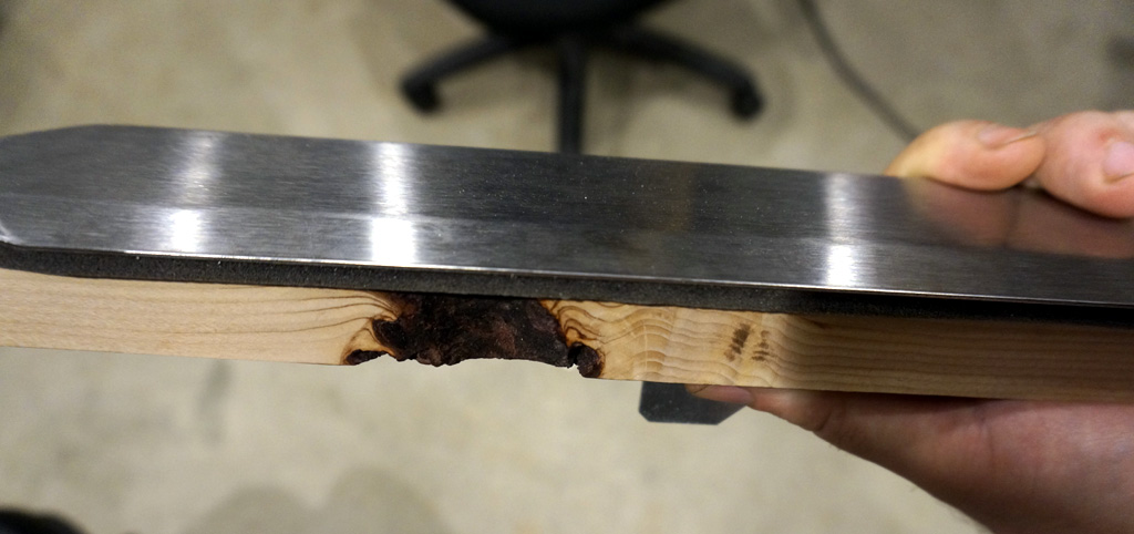
Knew that knot was going to be trouble.
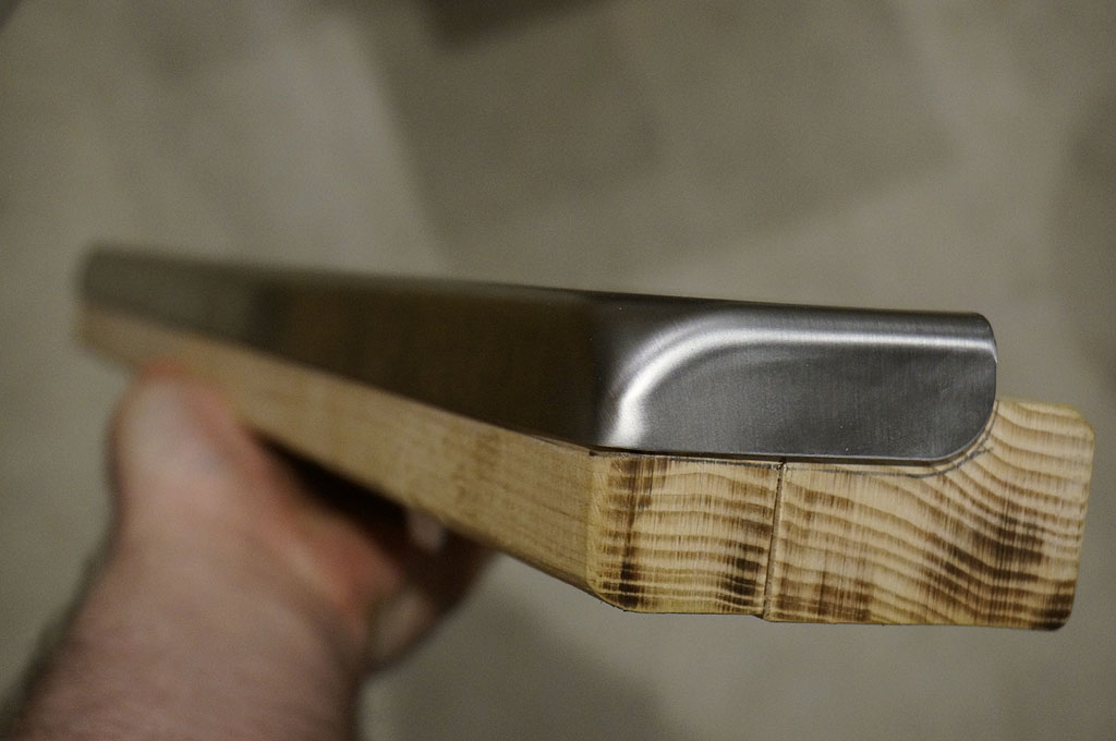
Here's the fully seated inlet piece with the 6' angle in it, and the back cut in another 1/4" so I can cover over that knot.
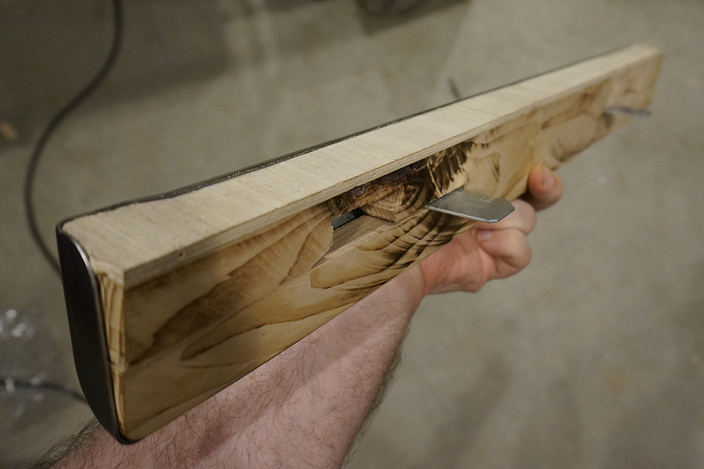
Skinned over the knot with plywood, and now at least one of my poor life choices is concealed.
The lockdown bar will plug onto the top of the front cabinet like so.
Meanwhile, back on the driving side...
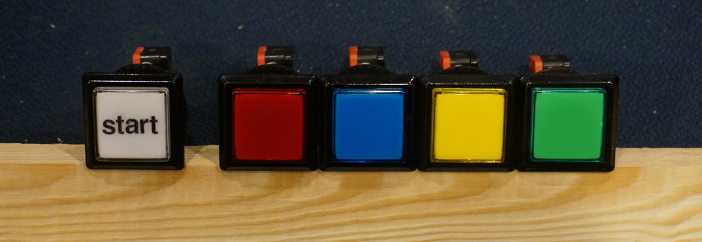
Several driving games used a panel of "VR" buttons for changing views or radio stations. These will be mine, which are not quite
the right size,but are at least the traditional colors.
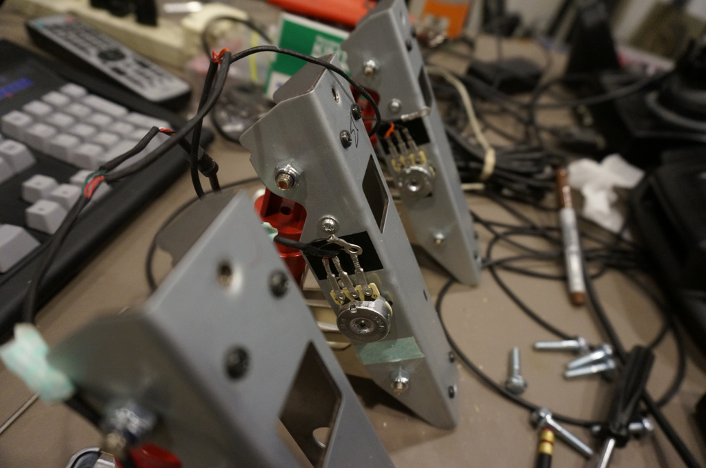
The cool thing about logitech G25 pedals is that they are seperate chassis if you remove the stupid plastic floor base that they come in.
I made my own frame to carry them, and to remount them upside down. Normally, they lever down toward the floor,
but they're built reversably so you can do a firewall type mount like this.
The brackets got a corner-ectomy so they'll fit up top.
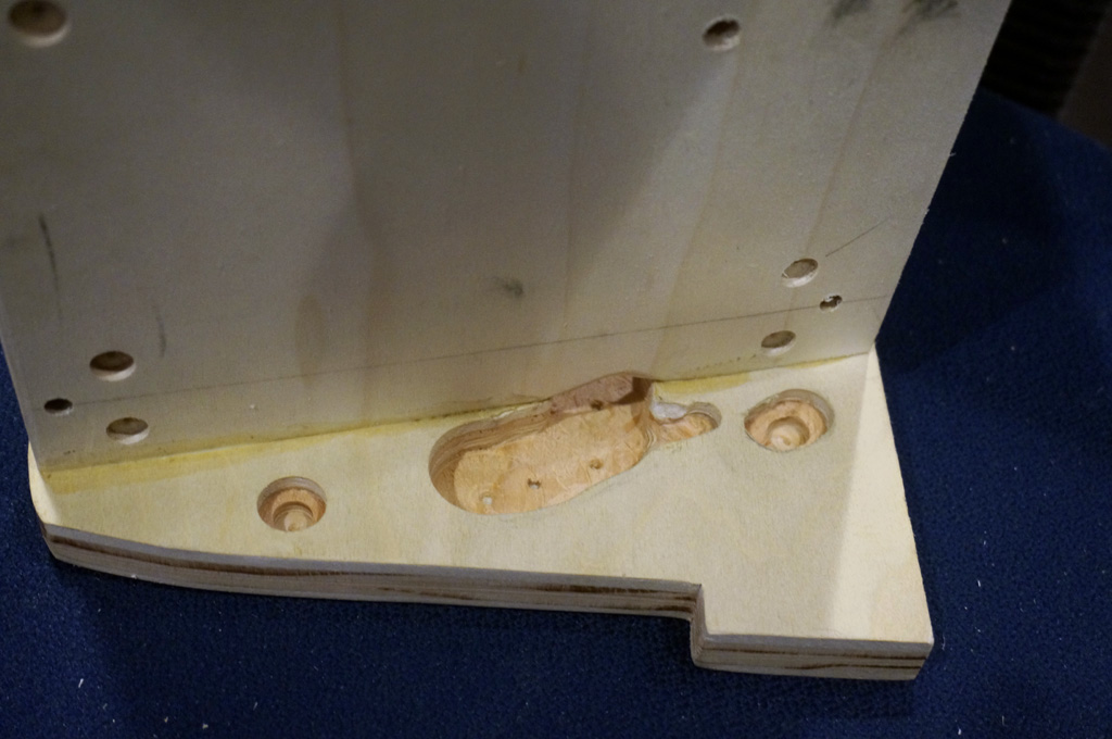
The wiring via allows the endmost cable to get to the protected back side.
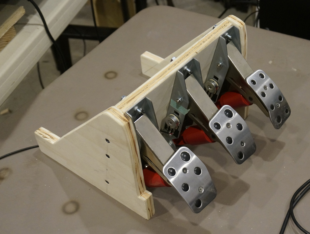
Here's the final pedal frame. It would have been simpler to make were it a bit bigger, but all the inletting results in a pretty
sleek little package.
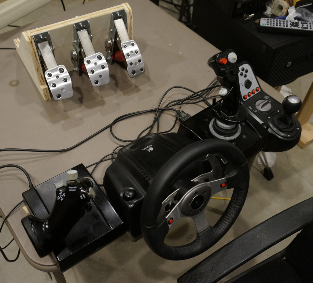
Here's all the main controls that will go on the sim side of things.
(Not shown, the coin door and the VR buttons.)
Continue