This is the log of building Shapeshifter - a one-off machine that is somehow both a full size vpin cabinet...
and also a sim-pit cockpit for flight simulators, racing games, and most of the sit-down arcade games.
(It's ambitious, but, I've already completed Mimic, so I think I may be able to do it.)
Previously...
So, the lockdown bar that you rest your palms on needs to be able to dock down into the front cabinet.
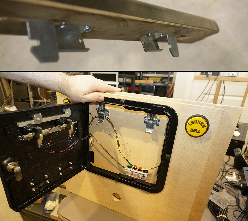
I don't have the necessary clearance to use the mating latch parts that normally talk to a pinball lockdown bar
and even if I did, the latch is surprisingly expensive. So I'll be using overcenter control panel type latches instead.
The clearance is zesty. The coin door buttons and the latches occupy the same vertical level
so this really is how much they don't touch by.
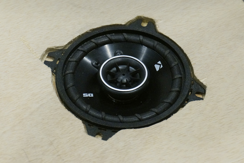
There's two inward-firing speakers for driving mode that the monitor has to be able to swing over the top of. So, they need some inletting.
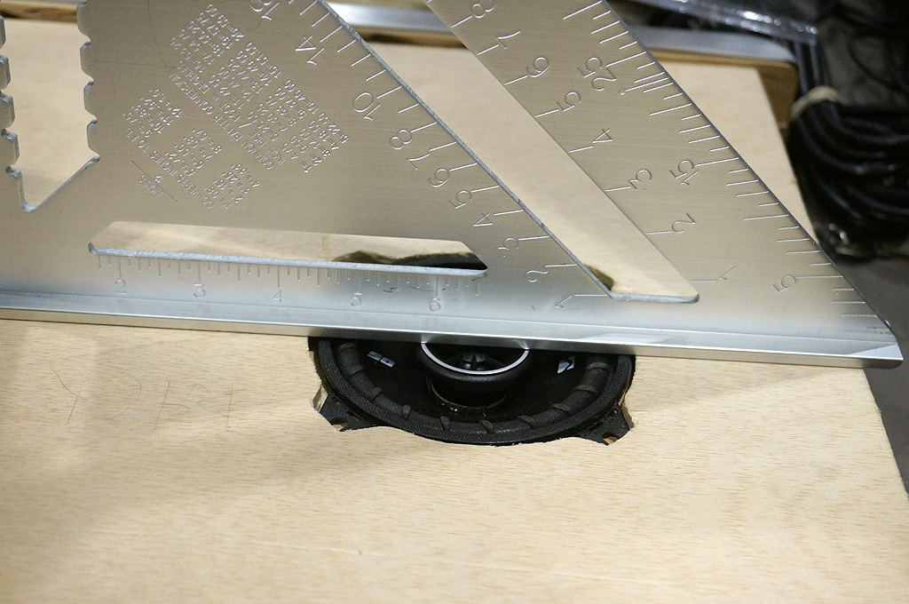
Yep, that's below flush alright.
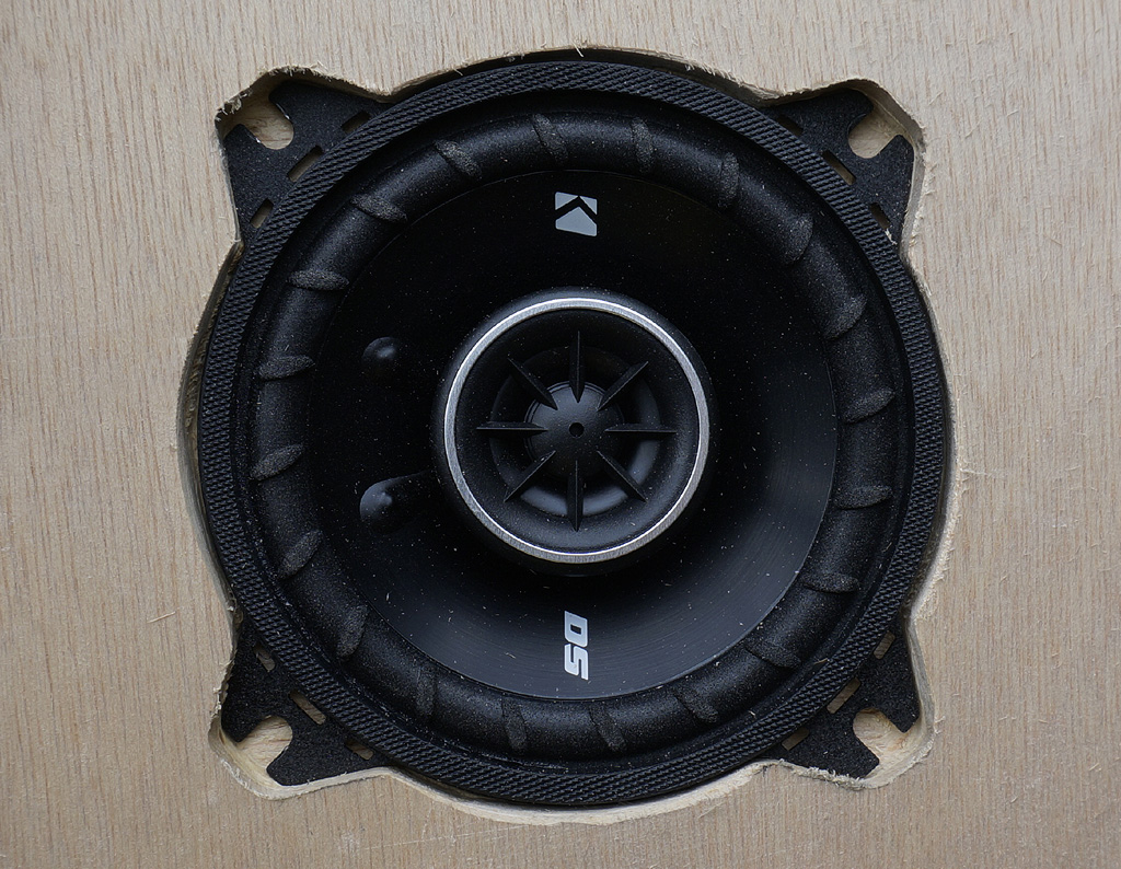
This is how I get a 4" speaker with a 2" below flange mounting depth to fit, recessed, into a 1 1/8" interior space box.
You can also see how close the magnet gets to the coin door.
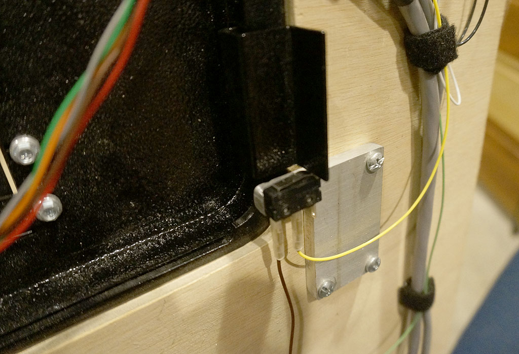
Real pinball machines have a safety switch that disables high voltage when you open the coin door, and enables the service buttons.
The emulator does this, but for the convenience of the host PC, changed it from an always-on
input to a toggle key.
I can work with that, but it means I need to blip a keystroke when the door is opened or closed.
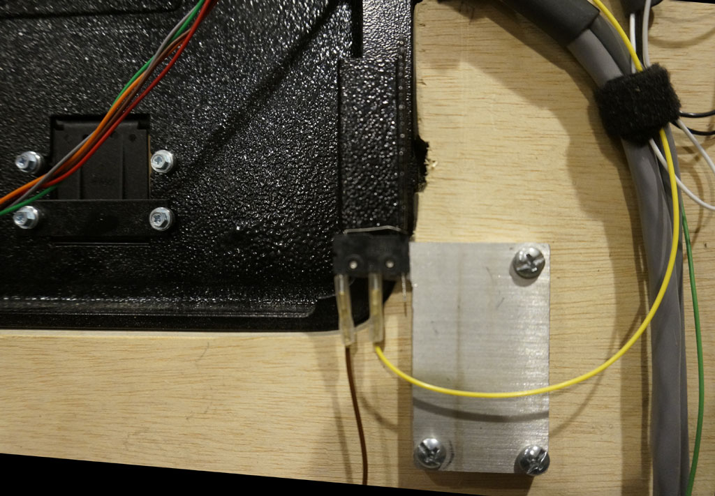
So, made this bracket and bent this switch. The flange clicks the switch once when it swings over it, and releases it again.
It's pretty cool to open the door and have the emulated machine react correctly.
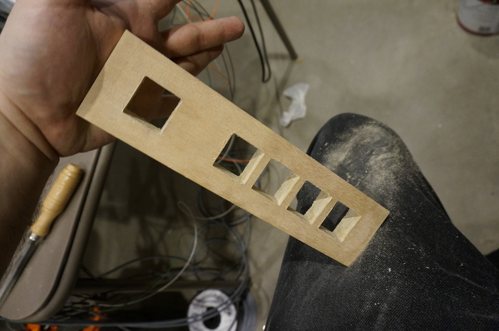
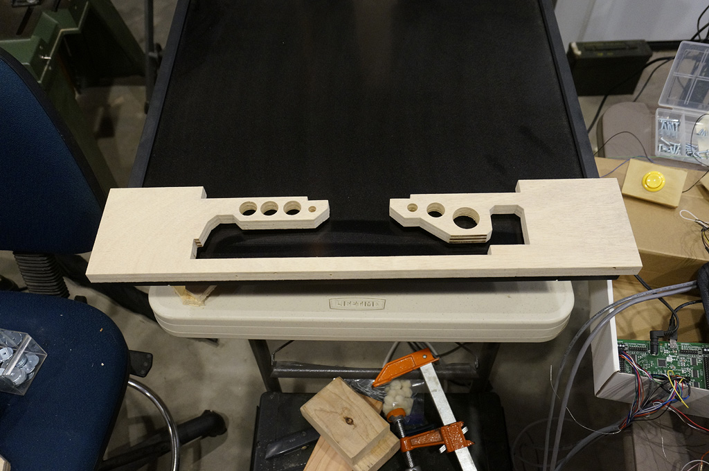
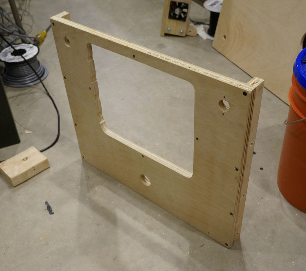
Here's the panel that will host those VR view buttons.
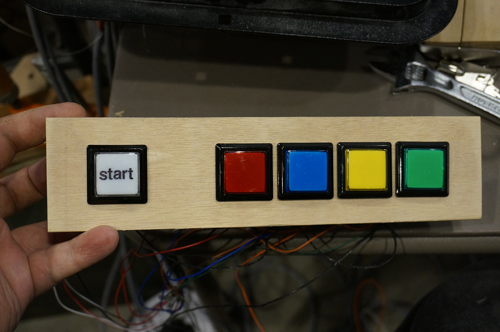
This will go under the "dash", over on the left.
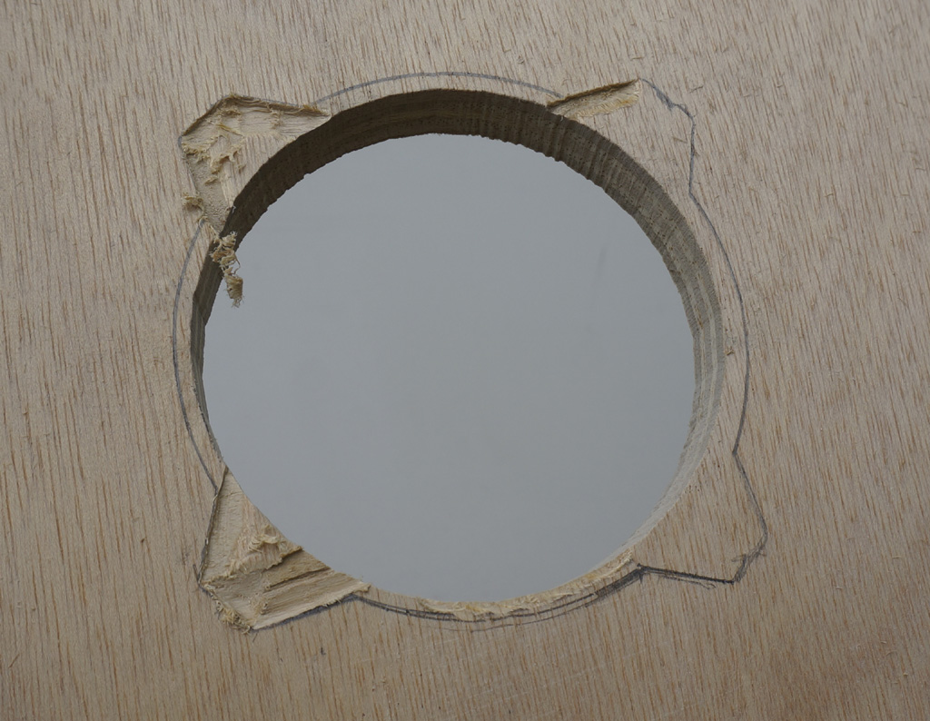
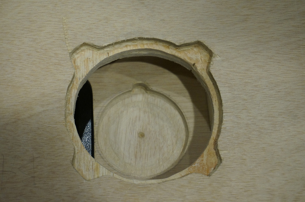
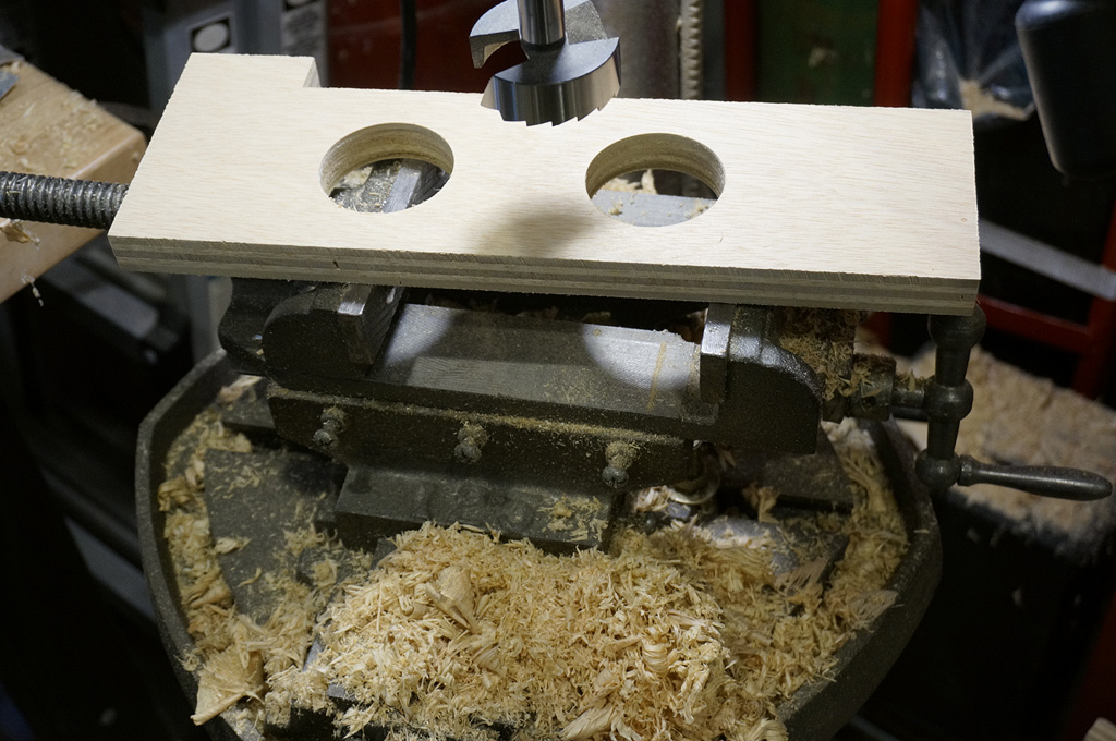
Doing the second speaker inlet, I took more pictures to show the process.
I do these with a dremel. First approach the lines with the front corner of the burr...
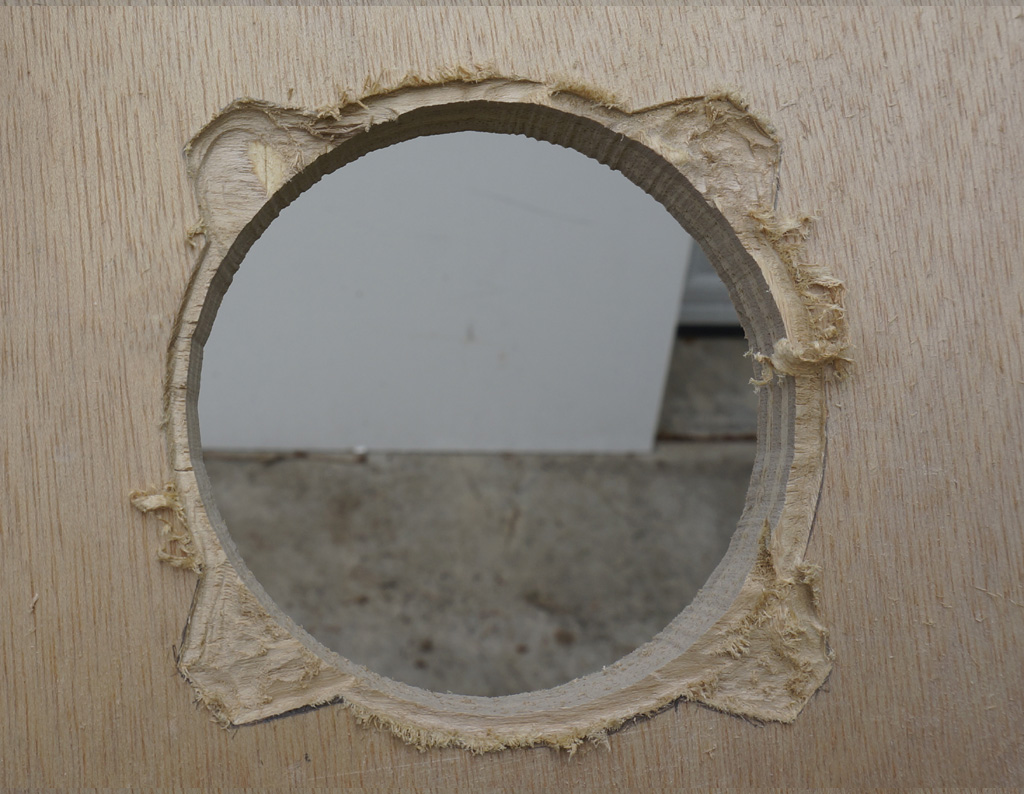
and just try to have faith this is going to work, because it doesn't initially look like it possibly can.
Plywood has a built-in depth gauge - you can see at the upper left where I've just touched the next layer.
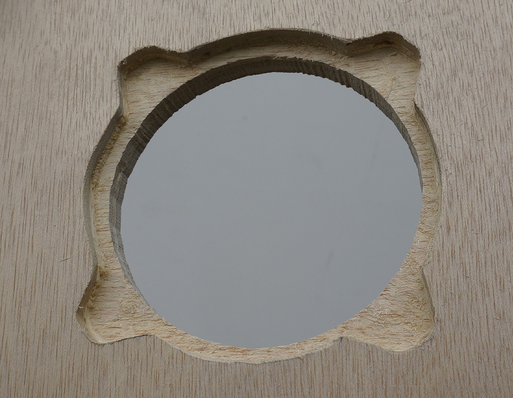
Stop when you expose the target layer, and you can get a nice flat bottom cut like this.
I'm getting pretty decent at this by the second one... which is probably the last one I ever need to do.
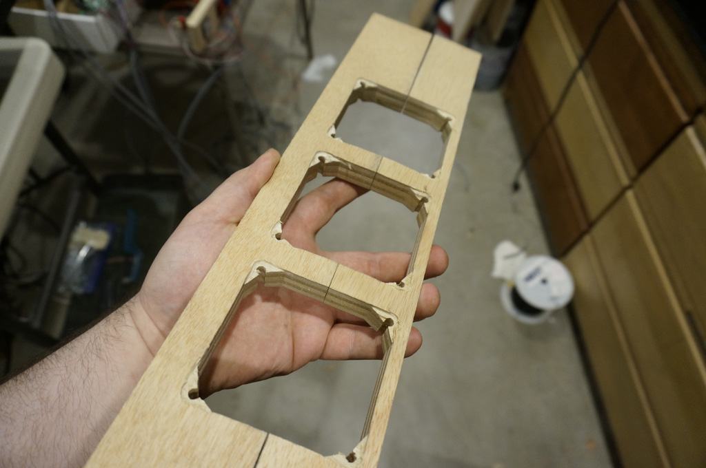
The 80mm fans in this design get completely buried inside boards. Turns out an 80mm fan's interior width between the H brackets is just
slightly less than 3/4" which means the ears have to be thinned just a little. More dremel work.
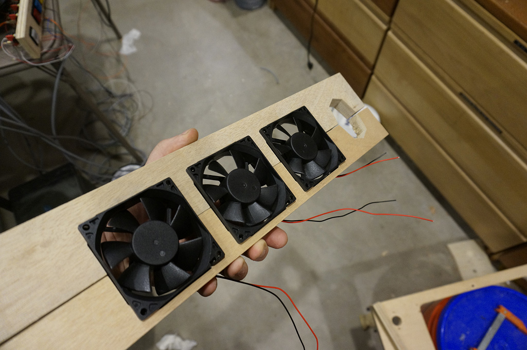
They fit in something like this. They'll also receive screws into the corners to keep them from rattling.
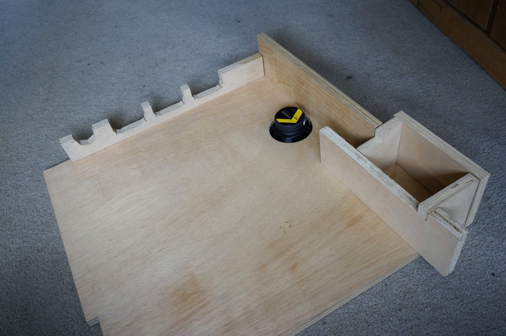
This is the beginnings of the lower rear cabinet, which will be under the bac/kbox, behind the playfield. It gets one forward firing speaker for
when the machine is in driving mode; a relay will eventually flip which speakers are active when it transforms.
Making sawdust. Lots of sawdust. These are wiring vias and access ports into the cheeks under the backbox - I don't know
what is going to be inside them, but it's internal volume, it might get used.
Sometimes feel like I'm making airplane parts, here. This is the floor of the backbox, which has a pass-through
for the DMD monitor, a pass-through for wiring, and a bunch of air holes for ventilation
to connect the wind tunnel between the intake fans at the bottom with the
exhaust fans at the top of the backbox.
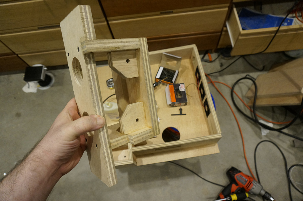
Here are the cheeks, as subassemblies. The chamfer-corner brackets have T-nuts behind them, to pick up the access hatch / back spine
via ten 1/4-20 screws.
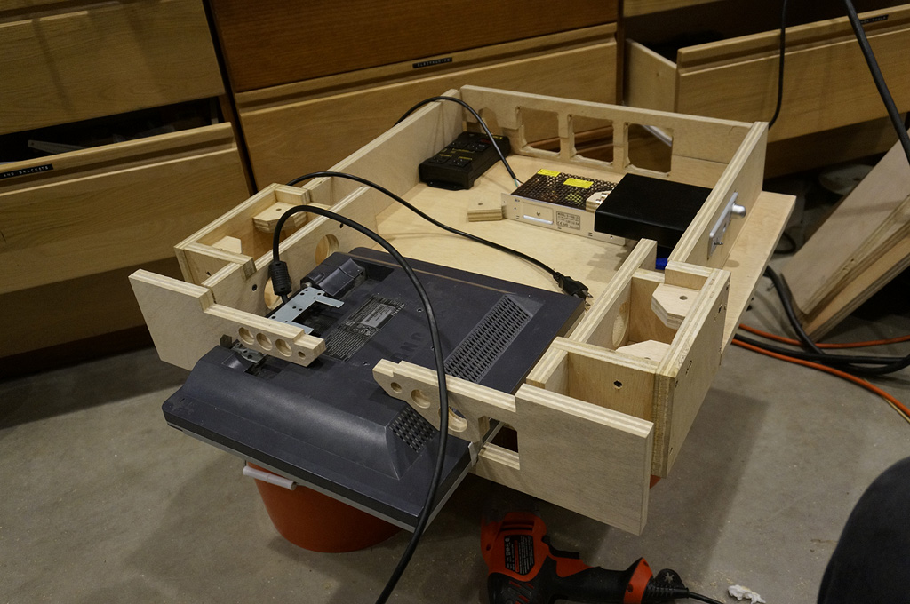
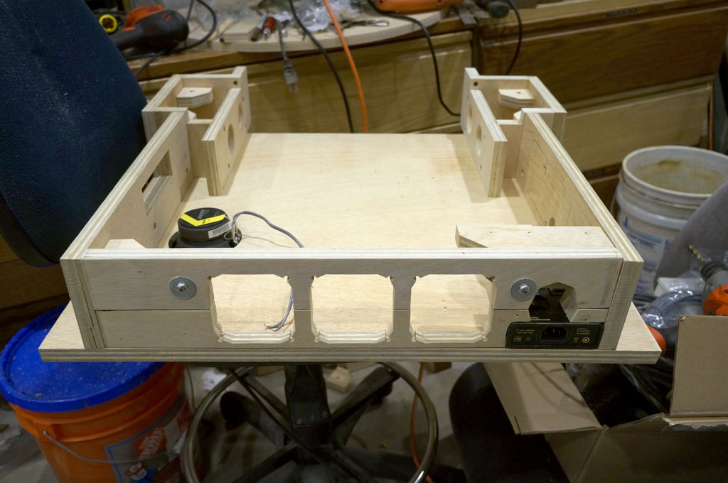
Here's some of the planned occupants, inside of the lower rear cabinet. The amplifier mounts behind the rear right
leg, with the volume knob and headphone jack accessable. The DMD monitor slides through the neck, hidden inside the lower cabinet,
with a skinny rectangle of fake DMD extending into the backbox. The three intake fans fire upward from the bottom, blowing
around the DMD panel for cooling, and up into the backbox.
The 3/4" flange standing up around the entire perimeter swallows and locates the 3/4" thick rear access panel, which will also become a structural
spine for the rear cabinet when fully attached.
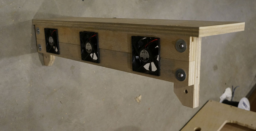
This is the roof of the backbox, with the three exhaust fans test mounted. The lower fan board can be removed, for
servicing the fans when one inevitably dies or starts rattling. The remaining chamfer bracket exposed
at the bottom will pick up the rear access panel.
I was able at this point to attach the sides to the front box, but I can't complete this box yet. I want the inside painted, and there
is absolutely no way to get in there to do it once assembly is complete.
This project is full of a lot of complicated sequencing traps for the unwary.
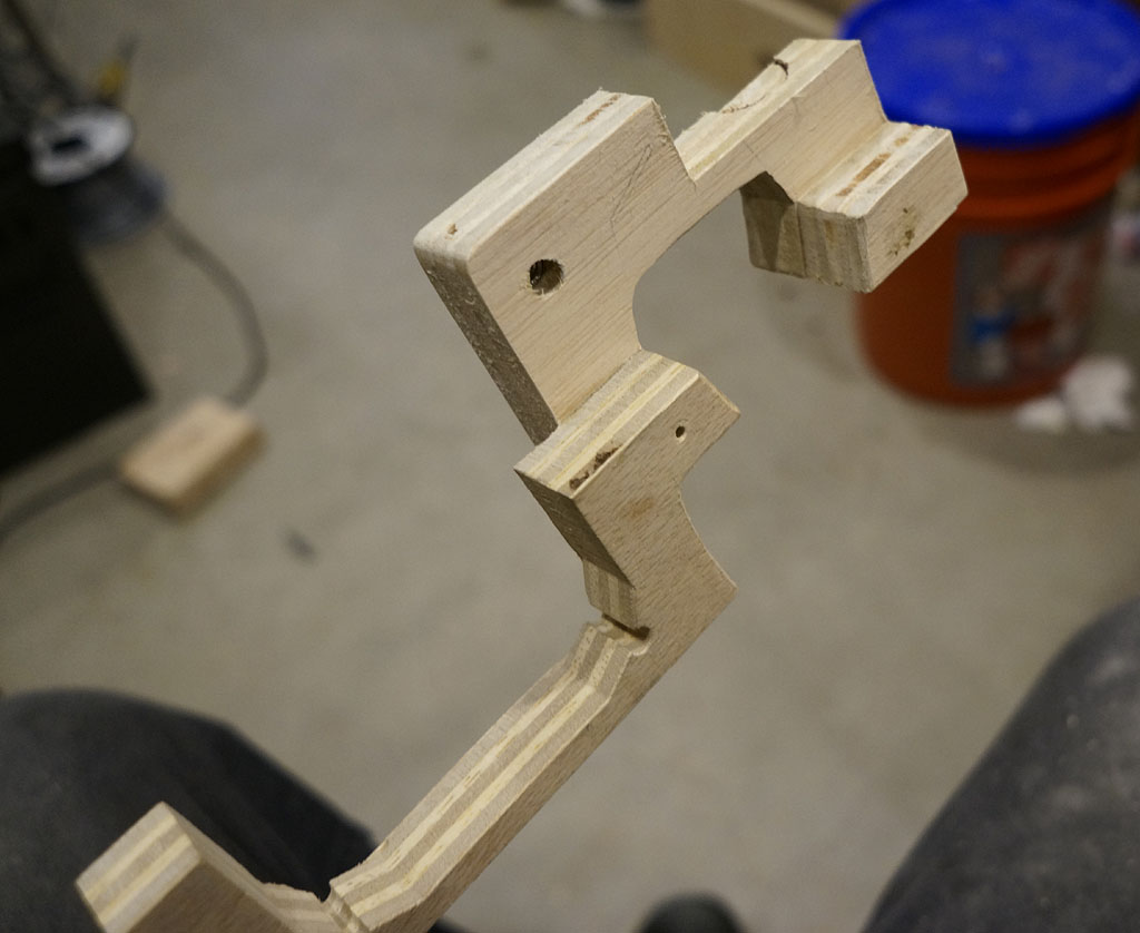
This may be the weirdest part I've ever made. Looking at this, I would not believe this to be the work of someone who had any
idea what the hell they were doing. This doesn't look like a part, this looks like the sprue that you cut your parts off of.
It makes more sense in context, though. It's the lower board of the fan intakes. Pardon the incomplete inletting, it's still
sitting up on the power relay, not quite on the plywood floor yet, so the right edge is raised above where it should be.
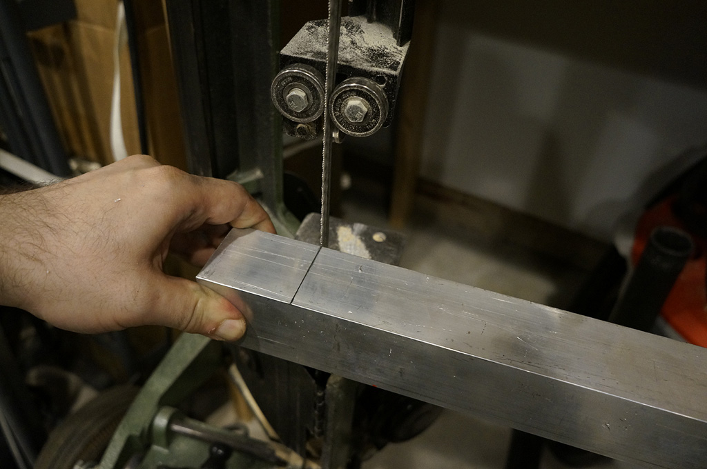
Time to make legs. Bandsaw to slightly over length - 34" on the rears, 32" on the fronts.
I can cut pretty square with the saw, but not totally square.
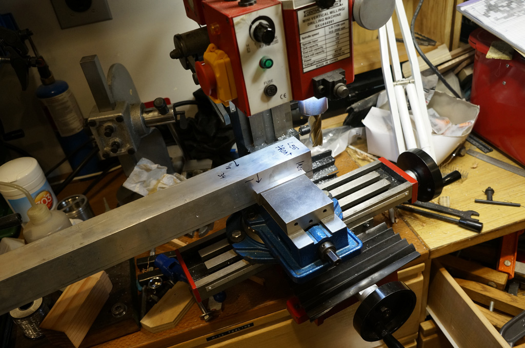
Luckily, I have square in a can.
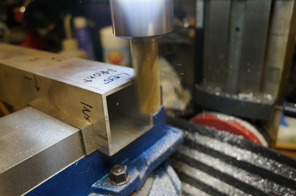
A lot of passes like this later, advancing down then resetting to the top and advancing in .005", and the end is no-but-seriously
square. Same thing on the other end, and work in until the length is also exact.
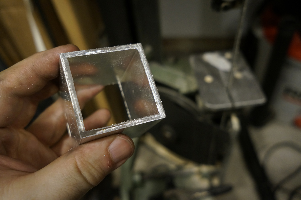
I don't want the legs to have visible hardware - I'm minimizing the visible hardware on the whole build, actually. So, I'm
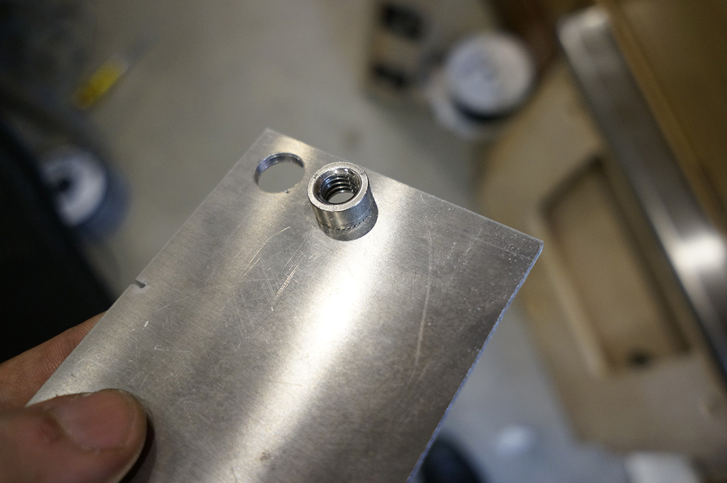
using PEM nuts. You are supposed to install them with a press, but in a pinch you can just pull them in by the threads. Here's the result, on a test piece of flat stock.
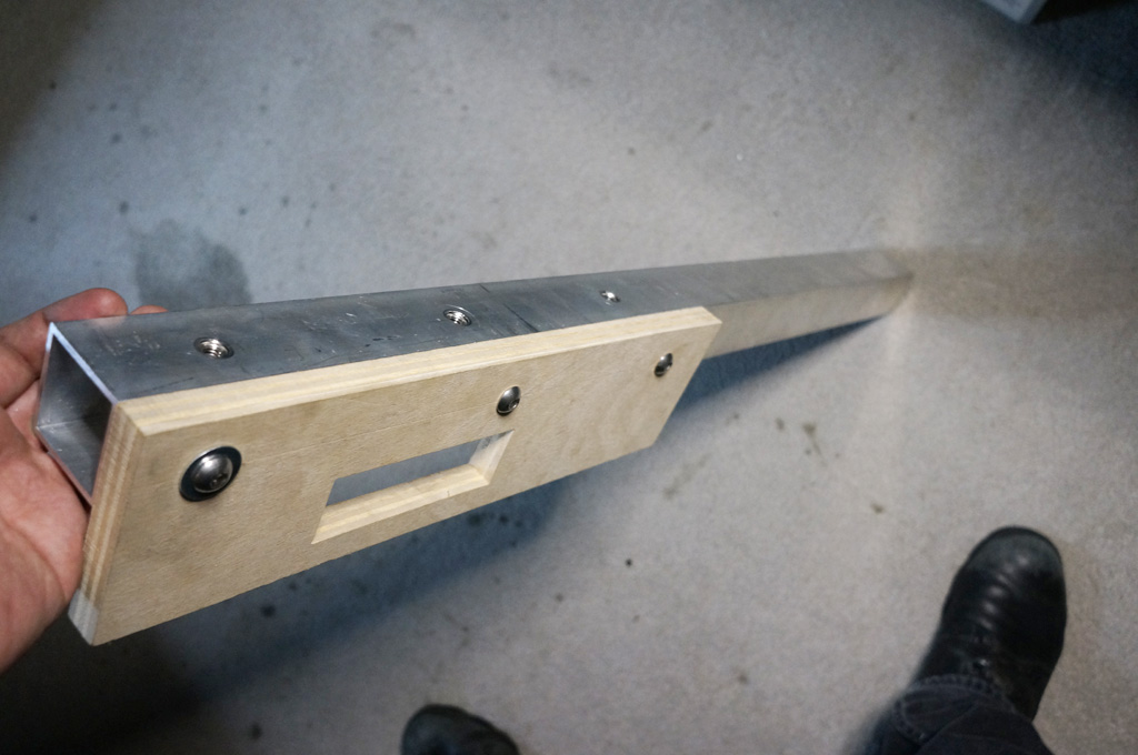
Behold, one leg. Now I just gotta do that three more times. Six 3/8"-16 screws per leg should be enough, right? :)
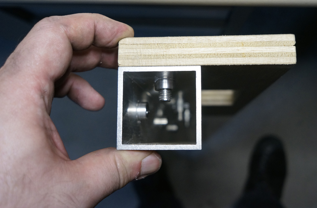
From the end, you can see how the hardware fits inside, and how nice the milled end cleans up.
Continue...