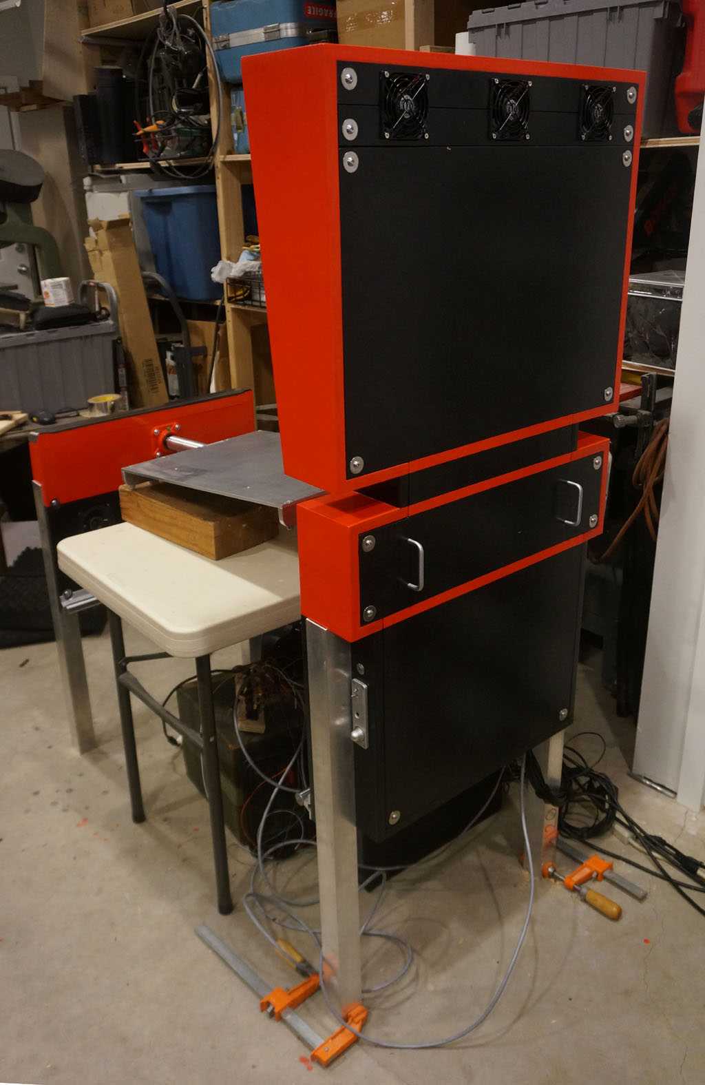
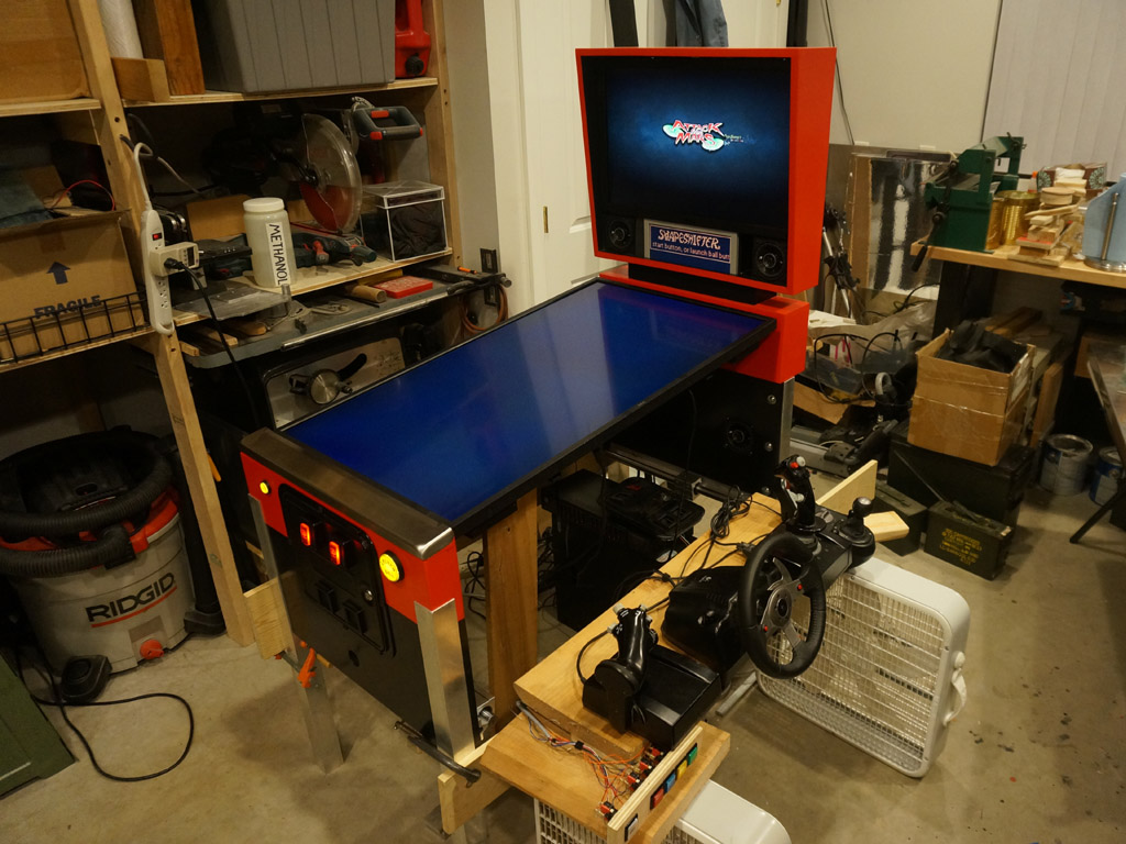
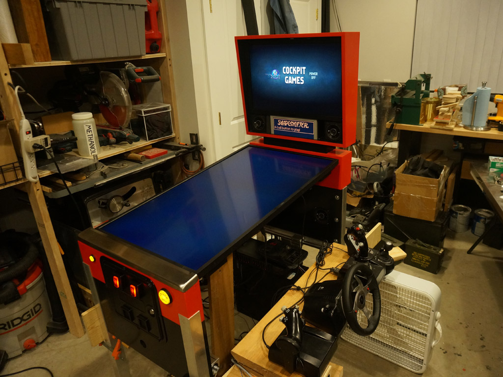
This is the log of building Shapeshifter - a one-off machine that is somehow both a full size vpin cabinet...
and also a sim-pit cockpit for flight simulators, racing games, and most of the sit-down arcade games.
(It's ambitious, but, I've already completed Mimic, so I think I may be able to do it.)
Previously...
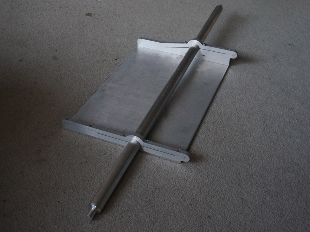
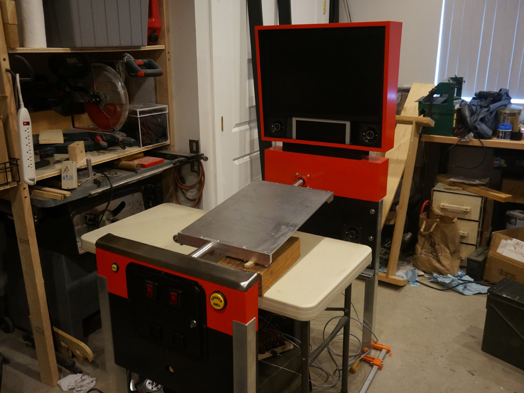
Now that I've got the axle complete except for cutting the tube to exact length, it's time to build the structure that rides on it.
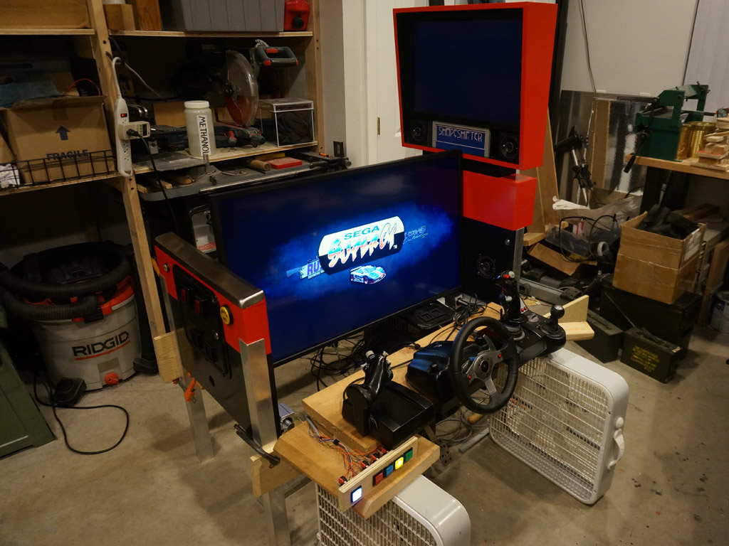
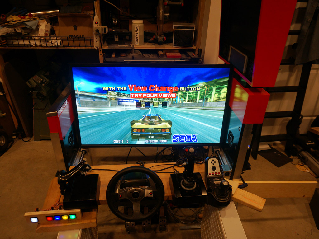
The axle tips up 3' and angles left 3'. The TV needs to mount on this tipped up another 3' and rotated 3' right.
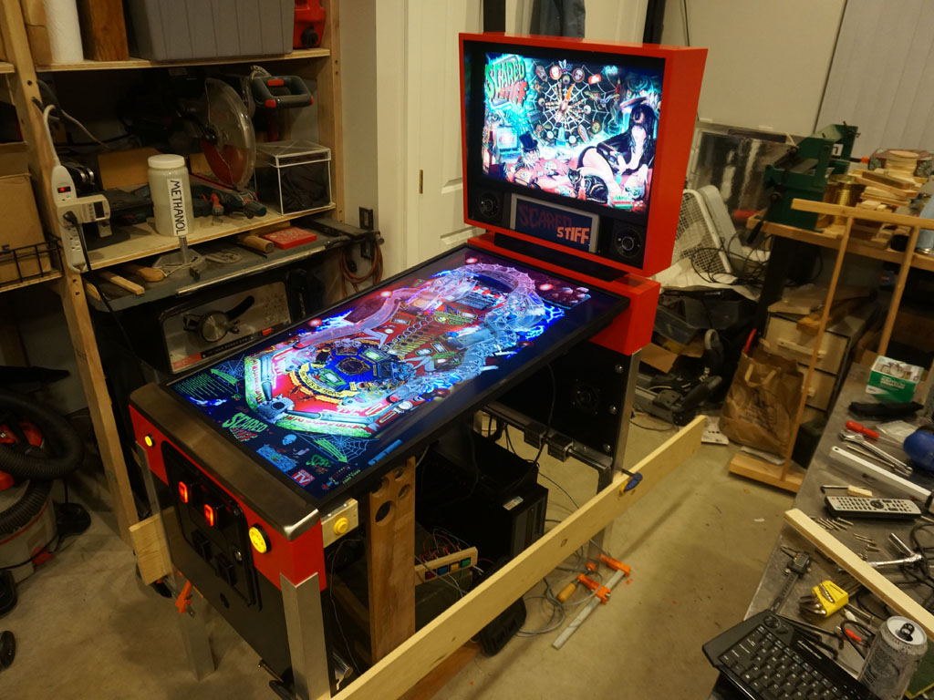
That way, in pinball mode, it's straight but angled up 6', and in driving mode, all the 3s cancel and it's straight and level.
That means I have to build a very carefully crooked mounting structure, which turns out to be quite a bit more difficult.
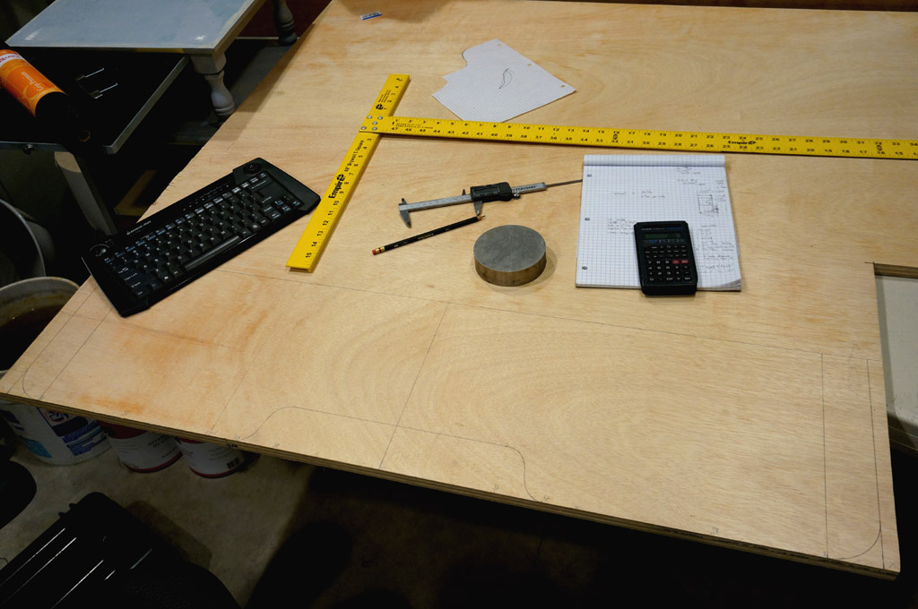
Here's the major parts:
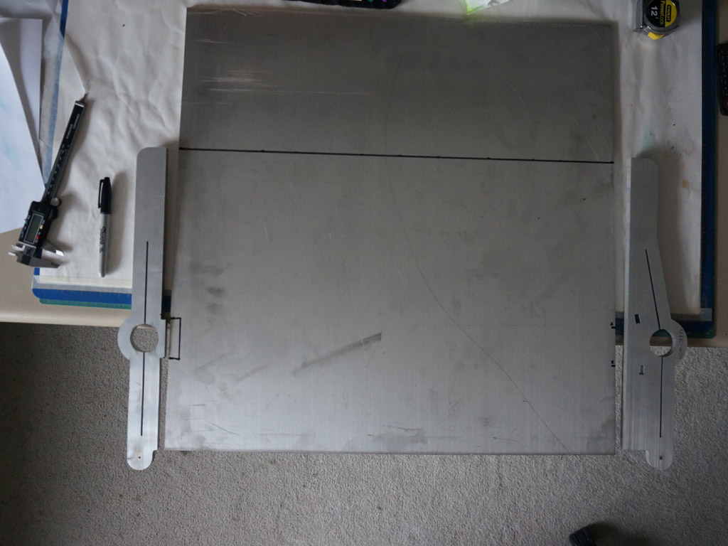
Jeff waterjet cut the brackets. Feels a bit like cheating, but man they sure turn out nice. Having the tool available, I
designed them in a manner well suited to the waterjet but fairly impossible to fabricate most any other way.
These brackets will clamp onto the axle, by squeezing the long slots together a few thou. If it weren't for the
waterjet, that wouldn't be a captive slot... it'd have been a two-piece clamp so I could get my bandsaw in there. :)
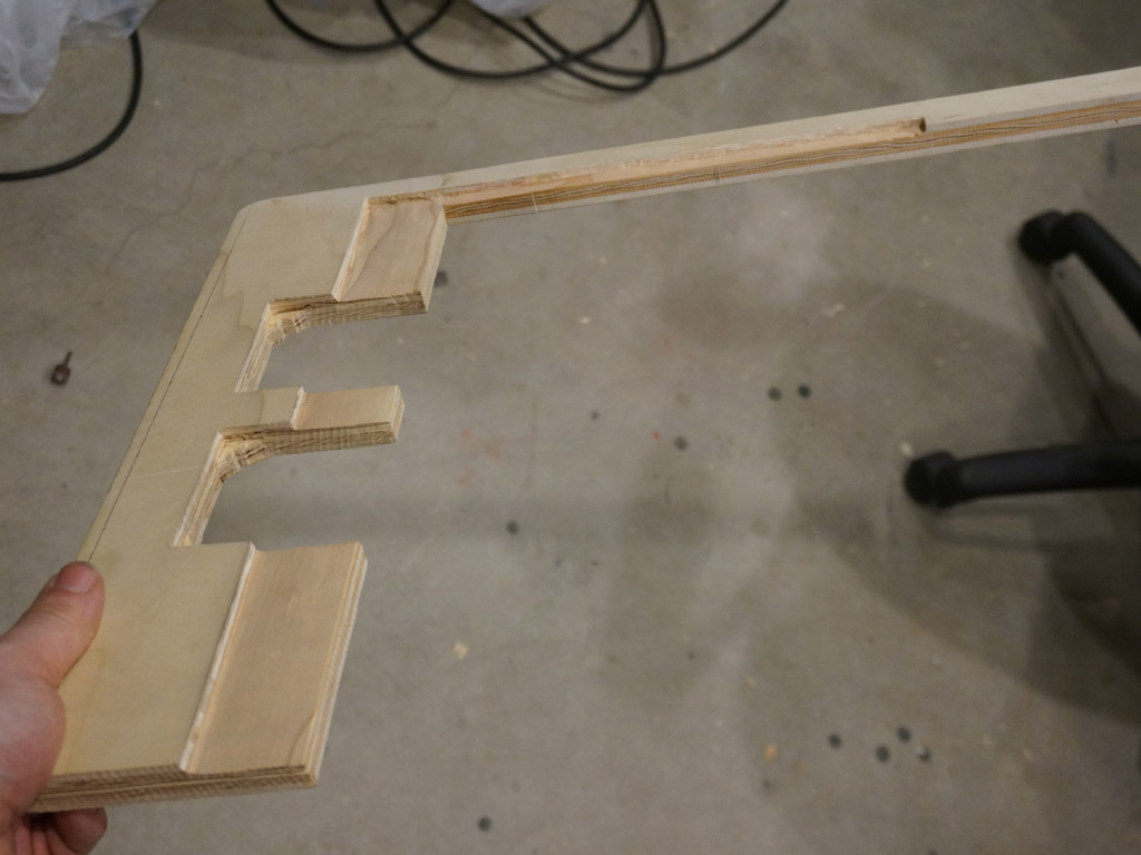
The bracket on the left is the one that runs closer to the player when in pinball mode, on the low side.
I didn't like how little metal would have been left between the axle hole and the deck, so I
put a dovetail there to gain the 1/4" thickness of the front plate around the hole.
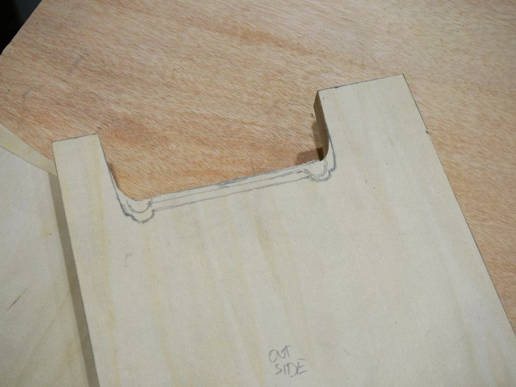
This dovetail requires a matching cut in the plate.
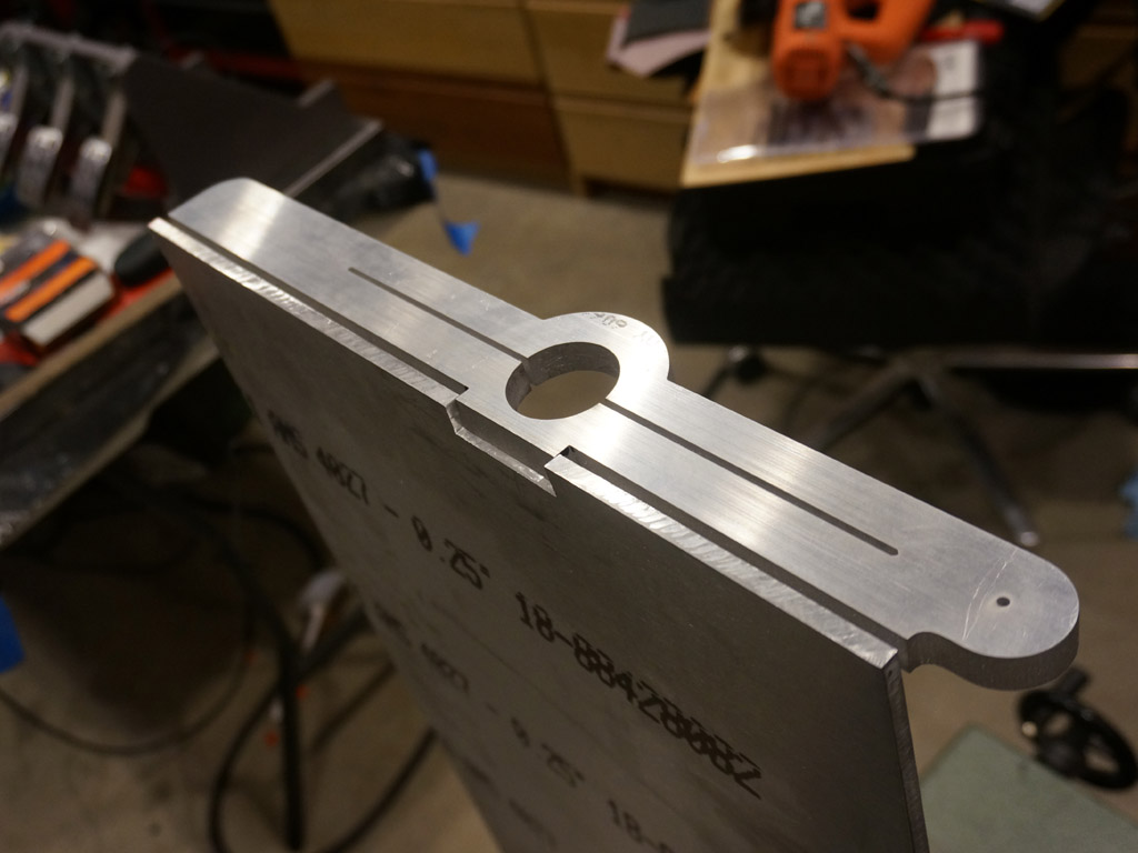
This is midway through me filing the plate to fit. The dovetail is complicated by the edge
of the bracket being cut at the matching 3' angle - these join up to form an 87' angle, not a 90'.
(It really is a dovetail, not just a notch - the top of it converges by the omni present 3'.)
Each of the brackets gets 5 holes drilled through it - the ones on the ends will clamp the
bracket to the plate, the ones in the middle close the clamps against the axle.
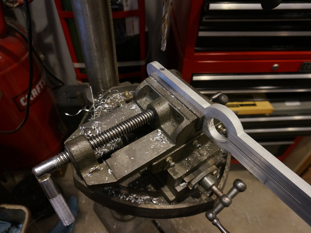
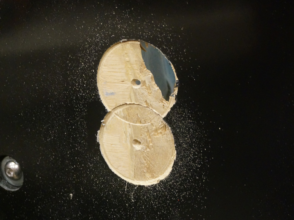
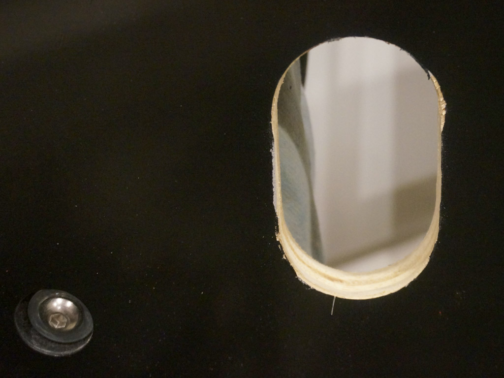
There's some fancy drilling to be done, with regards to those rectangular holes in the tall bracket. I wanted more
strength than I felt I could get from aluminum threads. Those rectangles are exactly the size of 5/16ths nuts.
So... just drill 2" deep, in from the top... and hit the center of those windows at the bottom.
Like that. 8)
Twice.
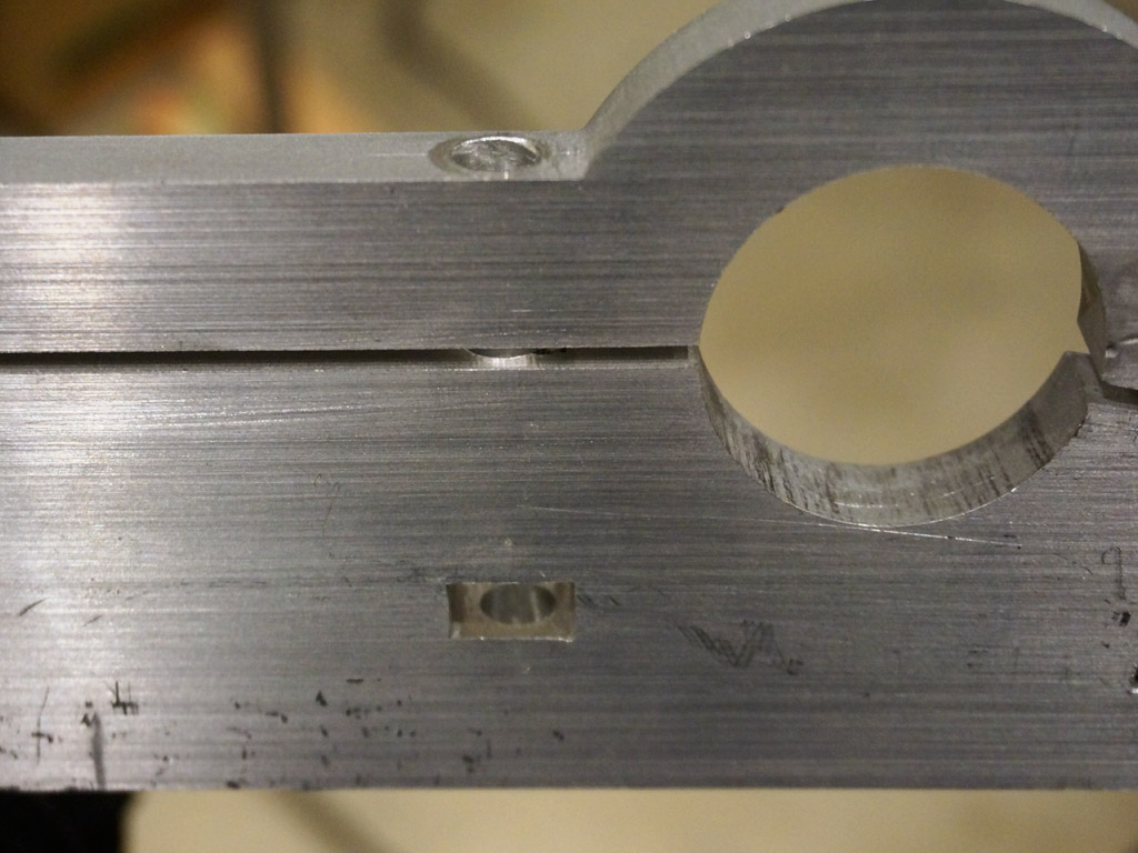
Result:
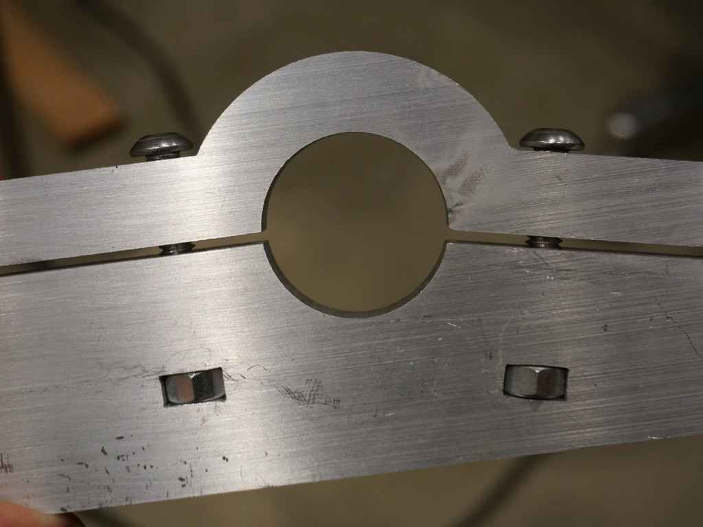
The clamping screws engage the nuts, the captive nuts can't turn because the rectangles are
only the flat-to-flat length, not the corner-to-corner length, and the threads are all steel-on-steel.
(I did have to nudge the rectangles a little with a needle file to get it all to work, I admit.)
I have yet to drill the countersunk holes in the plate to catch the heads of the hardware,
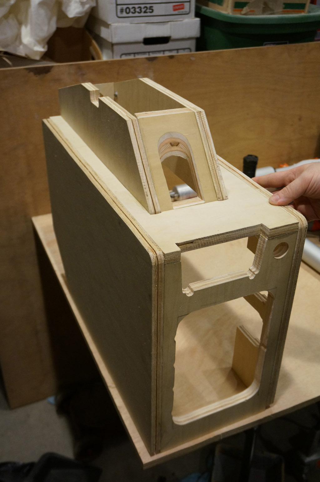
but with the parts set together to get a sense of how this subassembly will go:
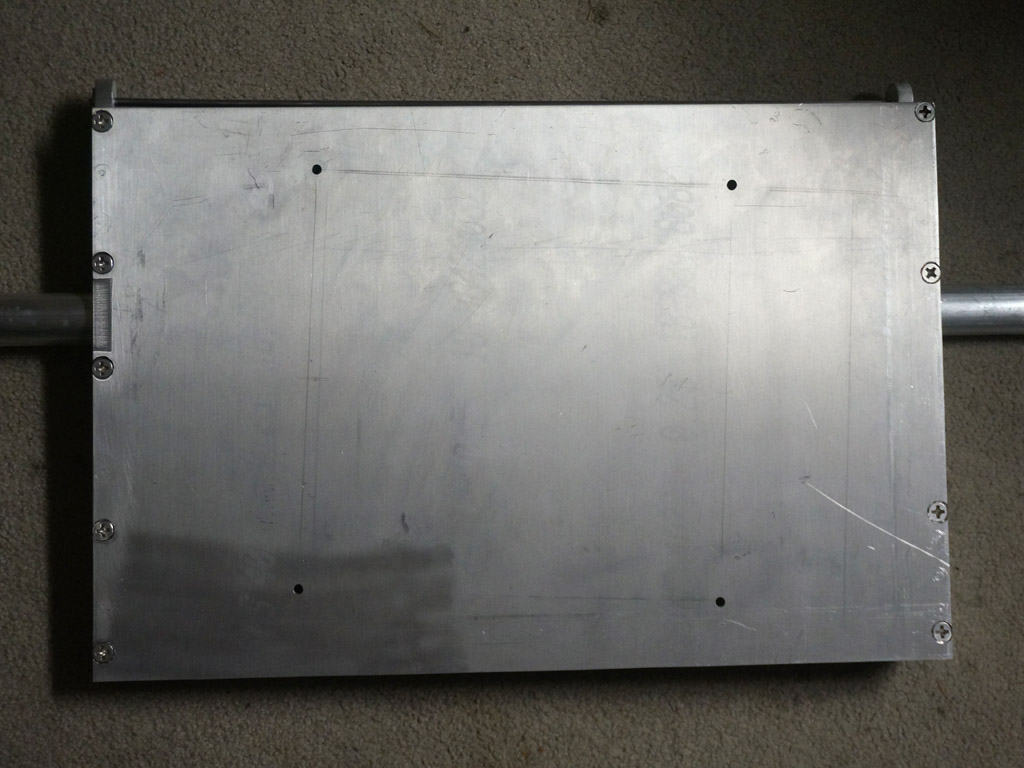
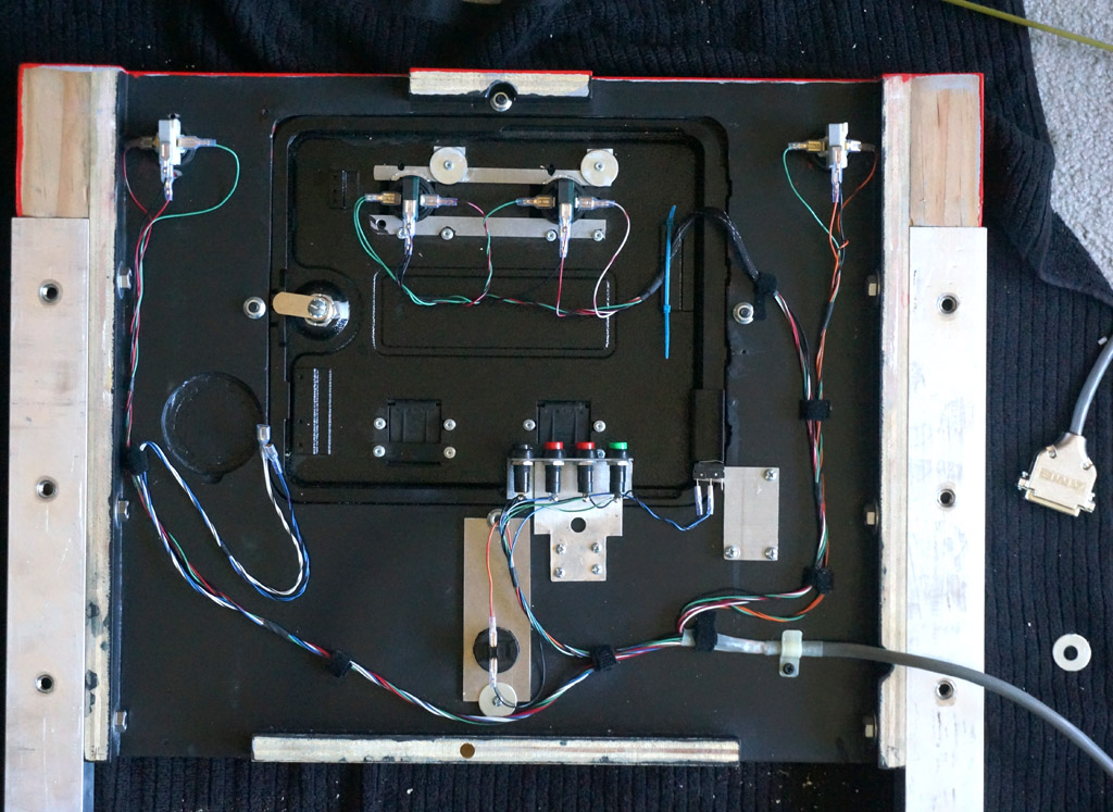
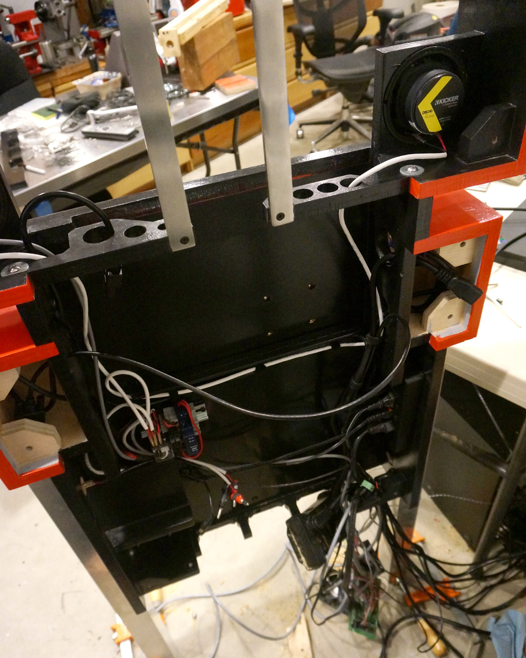
From the back:
All the empty holes will have the ends of machine screws (heads countersunk in the plate side) coming out of them, with nuts on top from this view.
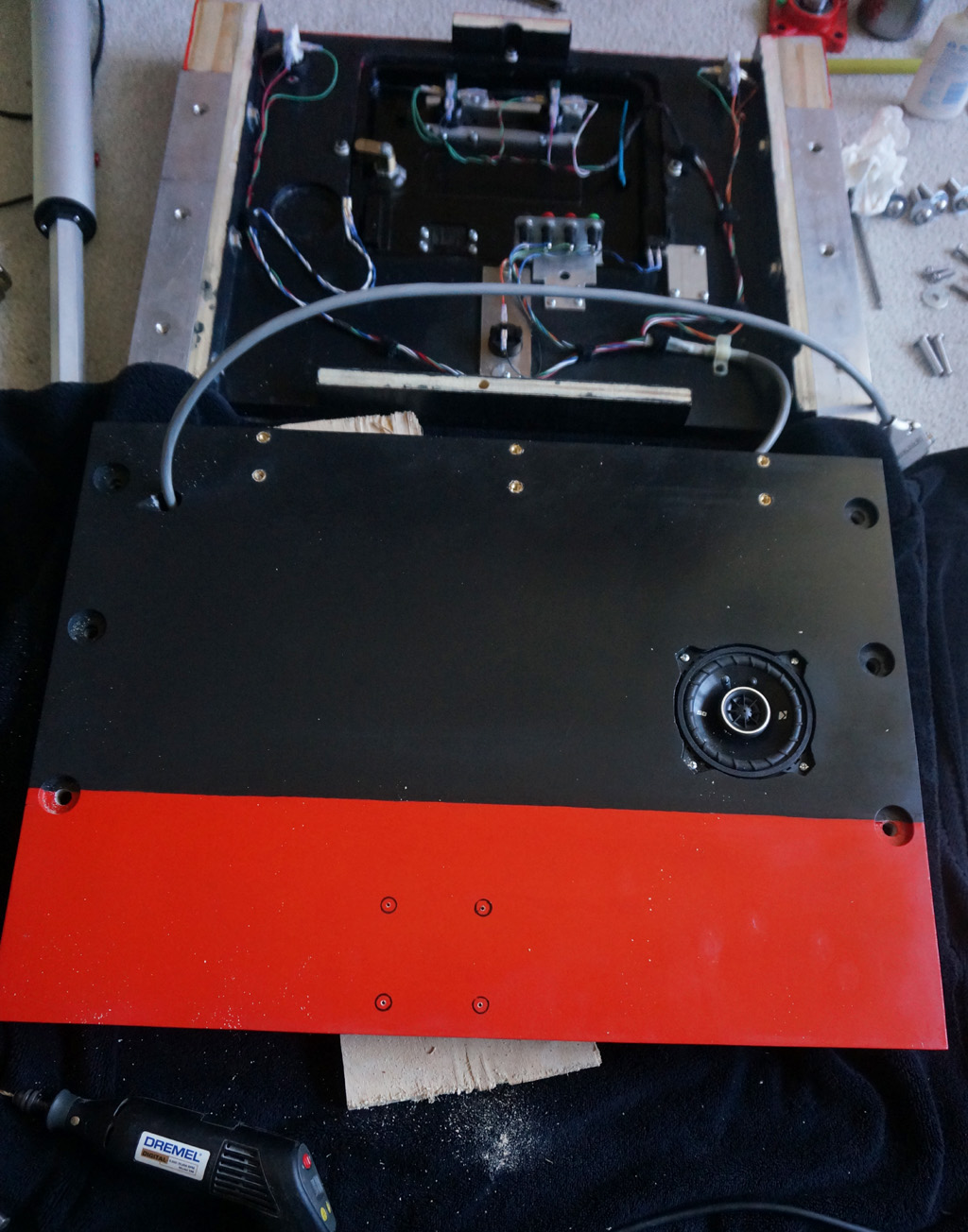
From the TV mounting side:
There will be 4 holes drilled near the center of the plate to take the VESA mount layout of the main playfield panel.
That pattern of holes, of course, will be rotated 3' clockwise off of square on the plate, to cancel
for the unwanted half of the axle tilt in each game mode.
This compound angle business is complicated.
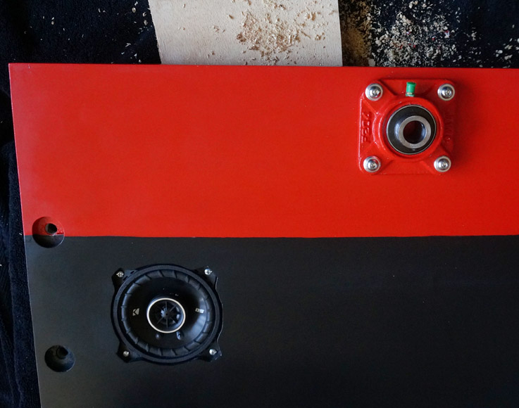
The semicircular ears you can see sticking off the top of the plate with small holes in them will be drilled out to pick
up a .250" spring steel rod 24" long, to form the bellcrank arm, the center of which will be grabbed by the linear actuator
that rotates the table. That should give it a little bit of shock absorption for the abrupt start and stop -
if that proves to be too much spring, I figure I'll just bring more additional mounts in closer
toward the centerline to shorten the effective spring length.
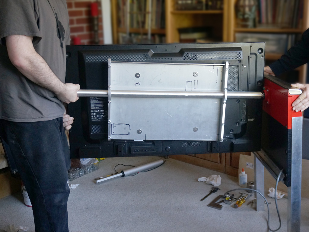
Still a bit more fab work to go to get the plate attached to the brackets. I'm looking forward to testing the bearing carrier
blocks mounted on the axle with the axle mounted to the TV, to check if my excitingly close clearance when
the corner of the block swings past the TV on the low side turns out to be positive or negative.
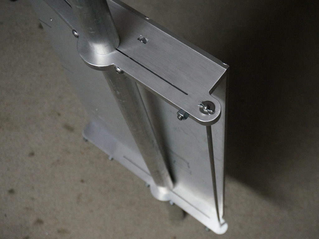
I probably made a mistake using this 5/16ths inch hardware in the brackets - you can see the edges of the heads of the hardware touch the edges of the plate.
The webs of remaining metal on the outside edges of all the countersinks are thinner than I'd like. It's mechanically sound - even if the webs had
blown out the plate would still be pinched between the screwheads - but I think the assembly might actually have been a little stronger if I'd only gone for 1/4" hardware instead.
I didn't blow out any webs, but there was some pucker factor toward the bottom of drilling out those countersinks deep enough.
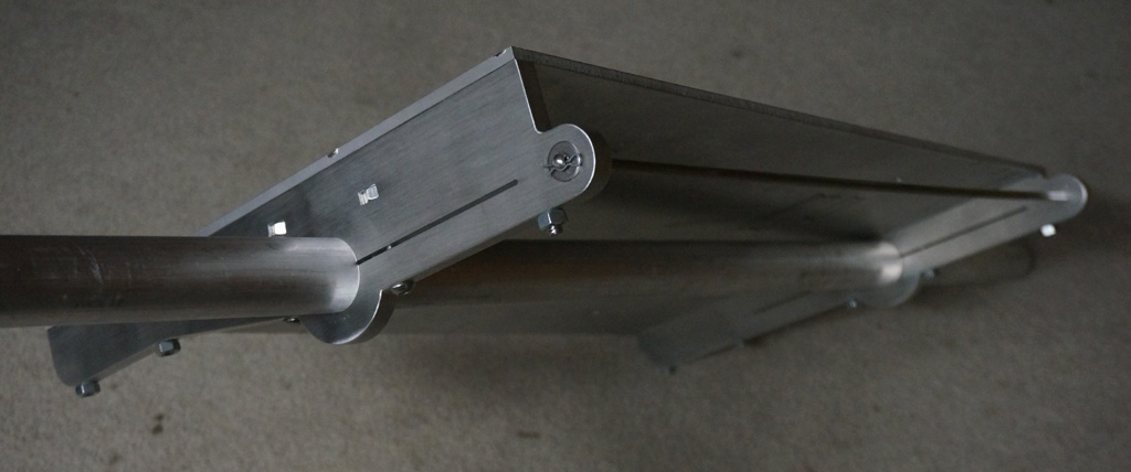
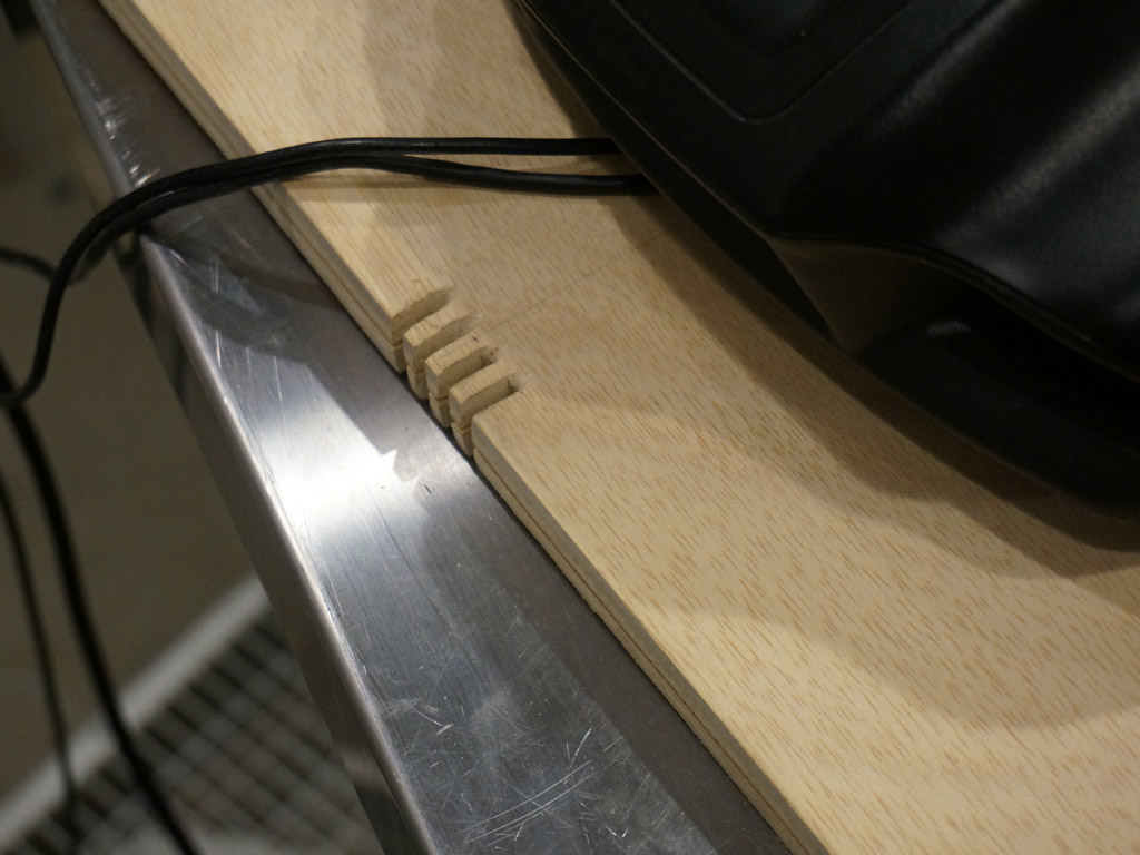
I also built the op rod that the actuator will grab; .250 steel bearing shaft, which has a nice spring to it, with domed ends, and crossways holes
for what I've always called cotter pins but which I just learned are probably correctly called hitch pins.
The pins sit over stainless washers to protect the aluminum.
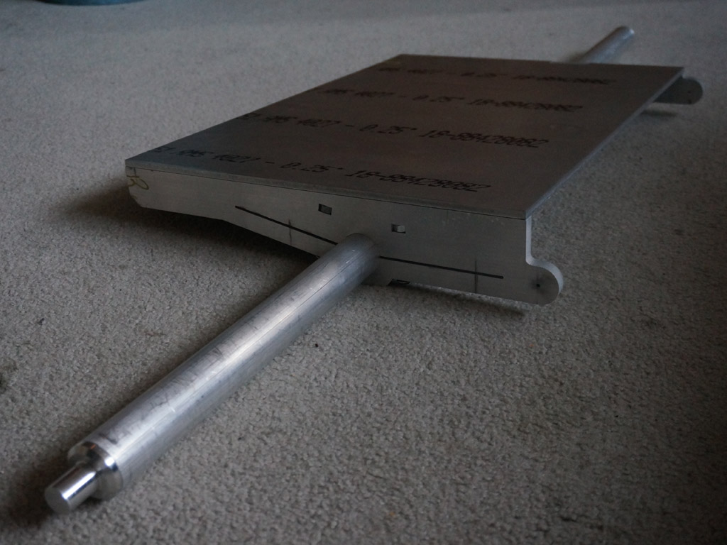
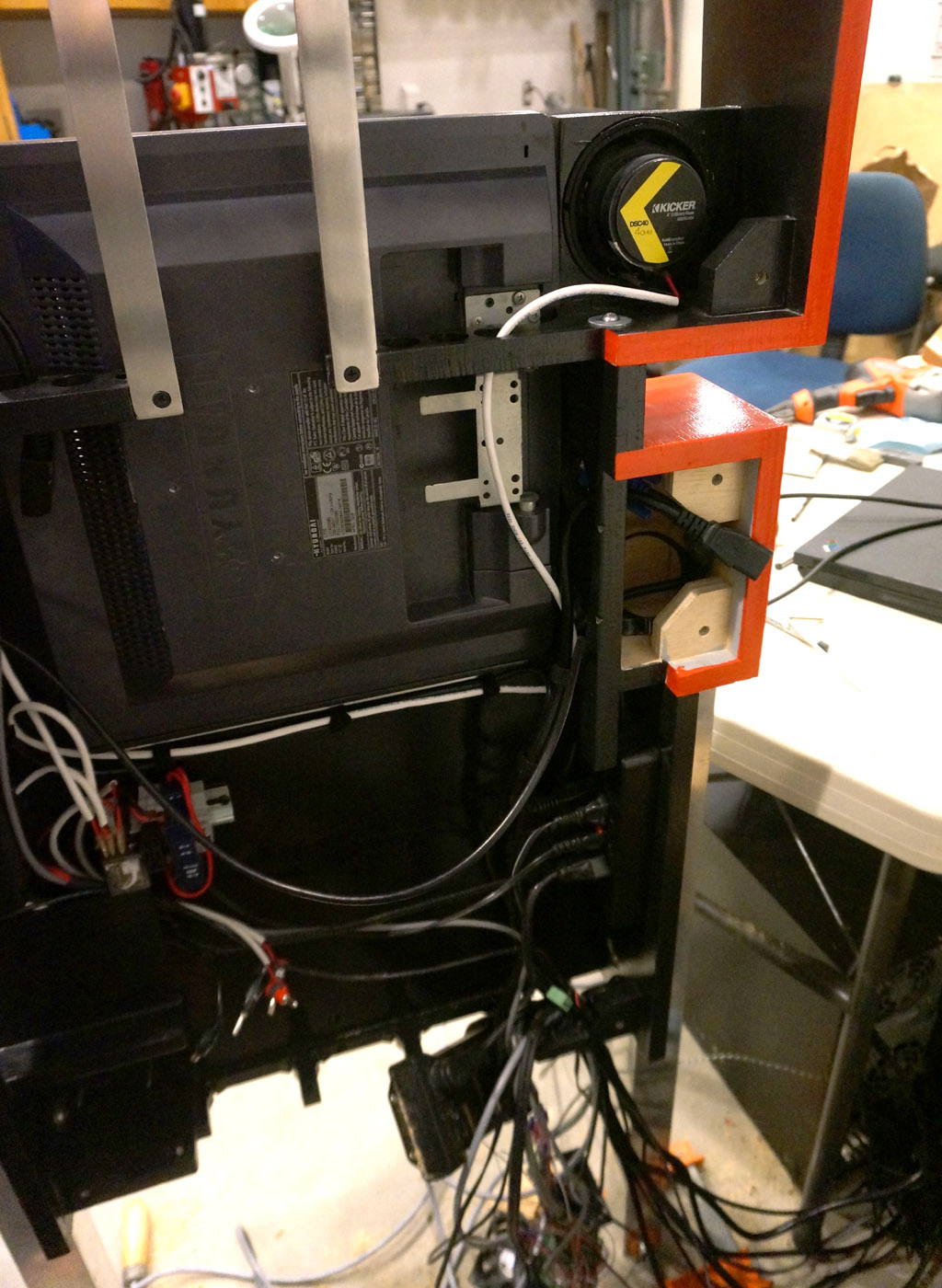
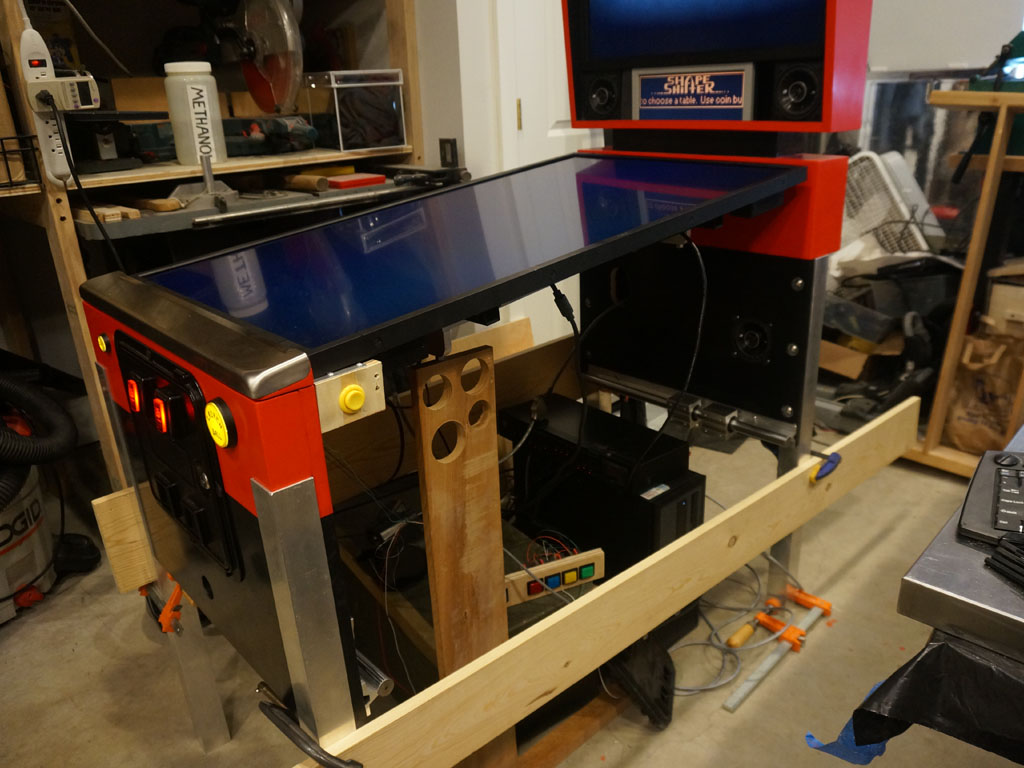
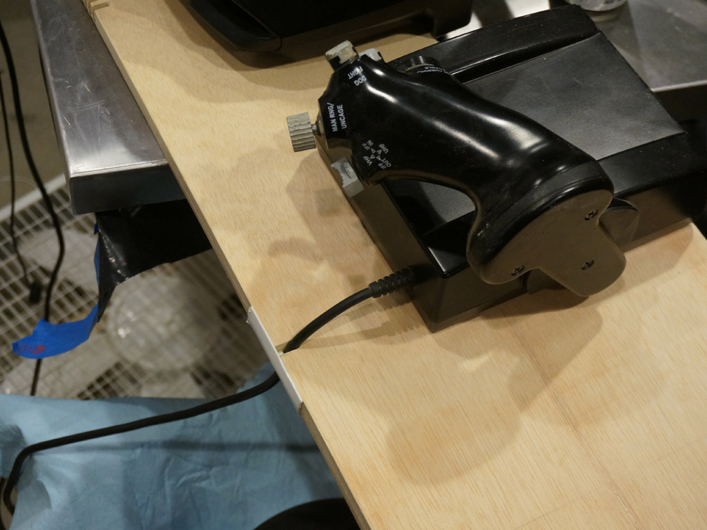
This oprod will slide through a bushing in the captive eye on the end of the linear actuator, and being able to slide it out to get the actuator out will make assembly easier. From the side here, you can see the oprod is parallel to the axle...
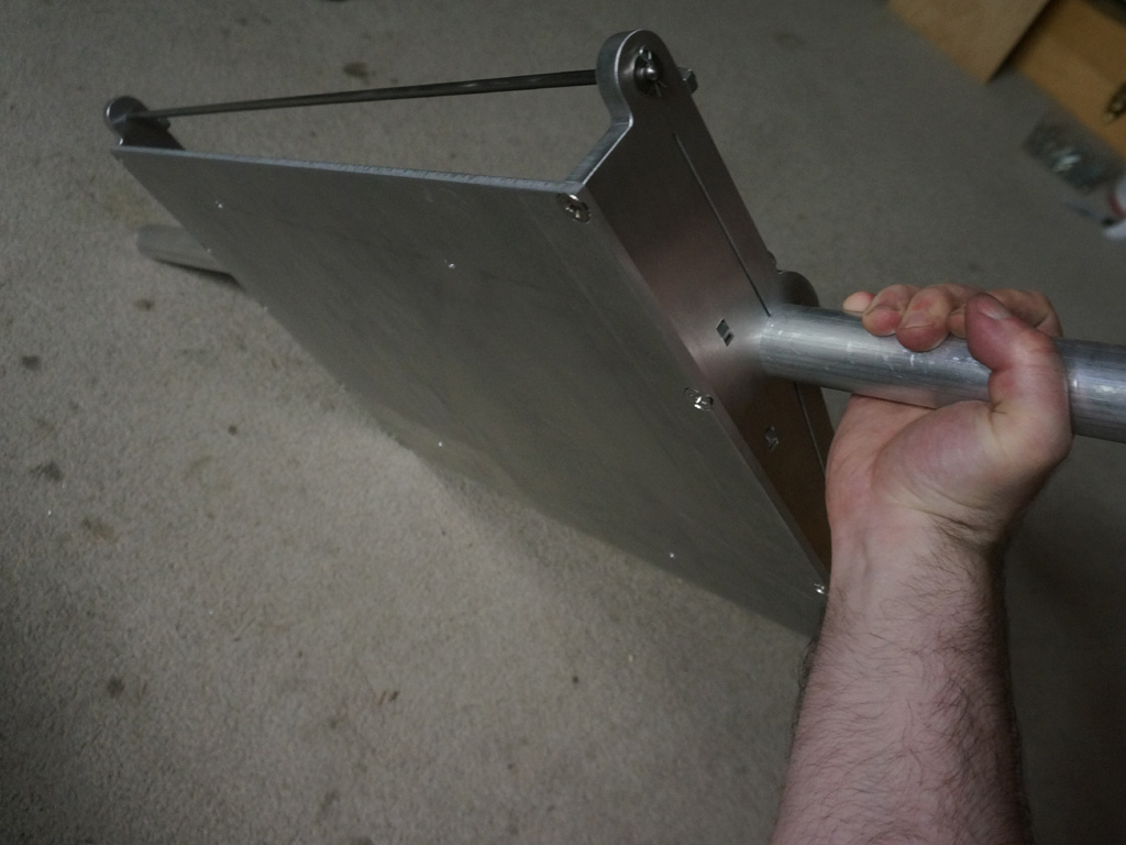
but from the other side, you can see the oprod is very not parallel to the plate.
I measured the exact axle length and boy it messed with my head. I know I've got a bizarre 42.33" distance cabinet to cabinet to make the room that the
angled monitor needs to sweep on it's compound offset angle, I know the bearing blocks are metric chinese parts with a spherical bearing that isn't flush
to the front or the back of the block, so I've got to allow for the height to the rotational center of each bushing plus the distance to the axle collar
ends when they are inclined 3' and skewed 3'... so I build a really high fidelity CAD model of all that to take measurements off, because I know it's
going to be some bizarre number...
... and it ends up being 39.5000"
This is like when you do your taxes and get a round number to the hundreds.
I tell you what, I triple checked my math.
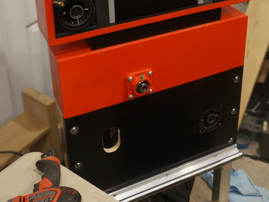
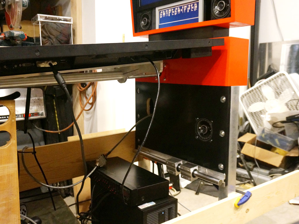
I've got the axle cut to that. I bolted the TV to the TV tray, and test fit the bearing blocks.
Turns out the clearance was negative, one corner of one bearing block will need ground back about 1/10th of an inch.
This all gets me close to being able to attach the bearing block carriers to the front and rear cabinet, so I got to thinking about the hardware for
doing that. The blocks have enormous holes, like they're expecting some kind of crazy huge 12mm bolts. I want to set these in thread inserts in the
plywood, same as the linear rails below, and I can't afford a lot of bolt head size because of the tight (already negative, in fact) clearance on that
one corner. So I decided to make up some spacers.
The eight spacers I need are all in this piece of round stock...
They just don't know it yet.
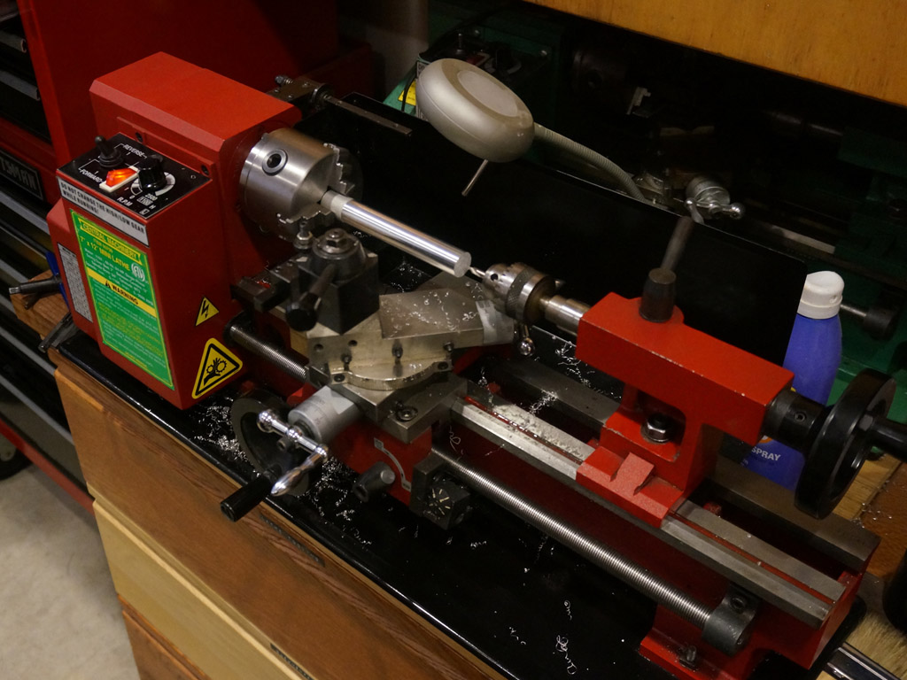
First I reduced the whole diameter to the 0.600" I figured I can fit into my final clearance, which I want for the outer flanges.
Occasionally, the lathe goes into self cleaning mode - if the curler coming off the tool interacts with the pile of curlers in the chip tray in a certain way...
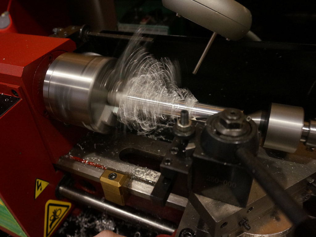
... the resulting birds nest spins with the part, scoops up all the loose shavings, and showers you with glitter and confetti.
Good times.
You can also see at the bottom of that picture a brass clamp I made a long time back.
This is an upgrade I made - it slides on the ways, and if you tighten it down, it forms a carriage stop.
Setting it carefully and locking it down lets me work confidently really really close to the chuck, like so:
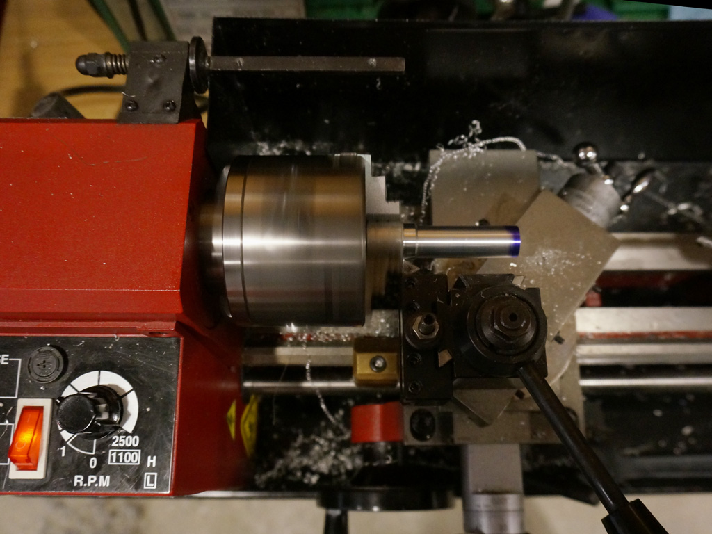
which I wouldn't have the nerve to do if not for it keeping me from moving any further left.
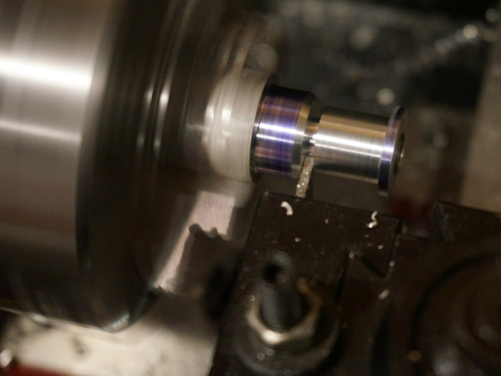
I kept working my way down the bar, drilling a bit farther, cutting the shape I needed, and then parting off each spacer.
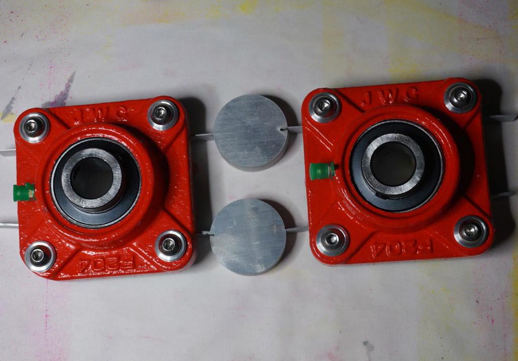
The result: 8x spacers that thumb-press into the bearing blocks, internally fit 1/4-20 button head machine screws, and look kind of nice.
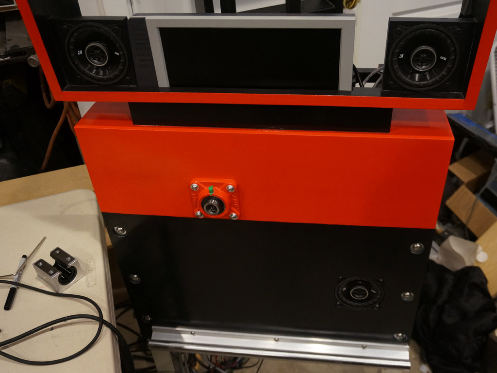
I ground the problem corner back, re-radiused it, primed it and painted it, and here's the whole kit together:
Here's a closeup to show the new contour of the block, and why it dictated the head size of these spacers and the hardware.
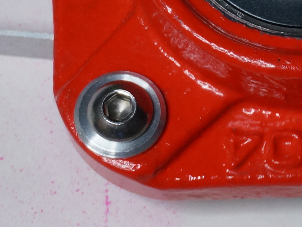
This contour now clears the monitor by about 1/16" when it rotates, and the spacer and bolt don't extend at all beyond it, so this should
work for the low side where things get tight. (No mods are necessary on the other block, the high side has got a mile of room.)

Continue