This is the log of building Shapeshifter - a one-off machine that is somehow both a full size vpin cabinet...
and also a sim-pit cockpit for flight simulators, racing games, and most of the sit-down arcade games.
(It's ambitious, but, I've already completed Mimic, so I think I may be able to do it.)
Previously...
While being able to play the thing is grand, it doesn't make for hardware progress.
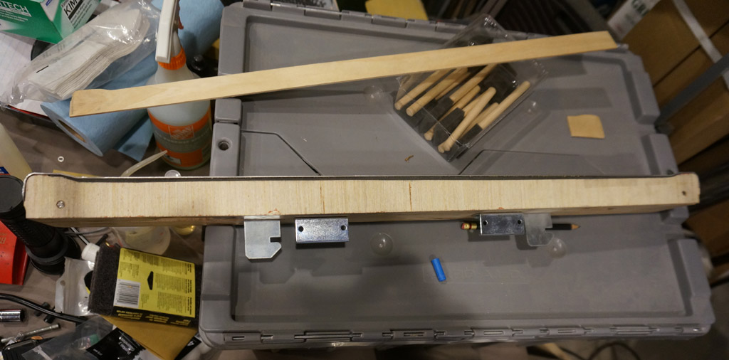
First up, the lockdown bar assembly needs work.
Back when I made the wood under the bar, I figured I'd just slice in from the ends to cut out some of the clearances on the bandsaw.
Unfortunately, over time, these fingers released some pent-up stresses and warped a bit, and the bottom ceased to be
flat across the gap. Additionally, I found that the lockdown assembly would look better if it was just a touch deeper -
if you flush it on the back edge of the front cabinet, you can see a step under the lockdown bar on the front,
and if you flush it to where the lockdown bar looks nice in front, there's a step in the back.
Some adjustments were called for.
First, I drilled and pinned it on both sides. I could have used a dowel, but I had some 1/4" stainless round stock handy, and
nothing says "STAY" quite like a steel pin. I also profiled two pieces of hobby plywood to fit - sheets are only 24" wide
and the bar is 25", so a splice was required.
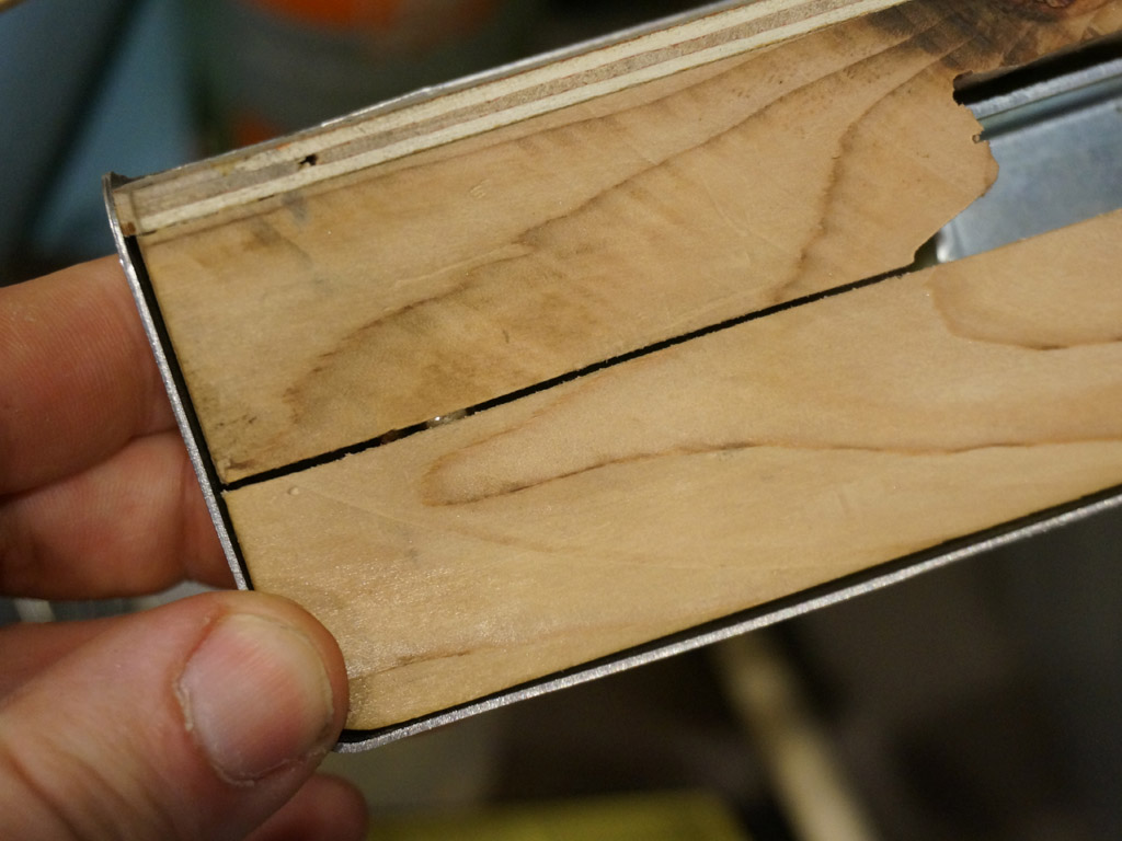
You can see the pins bridging the cuts here.
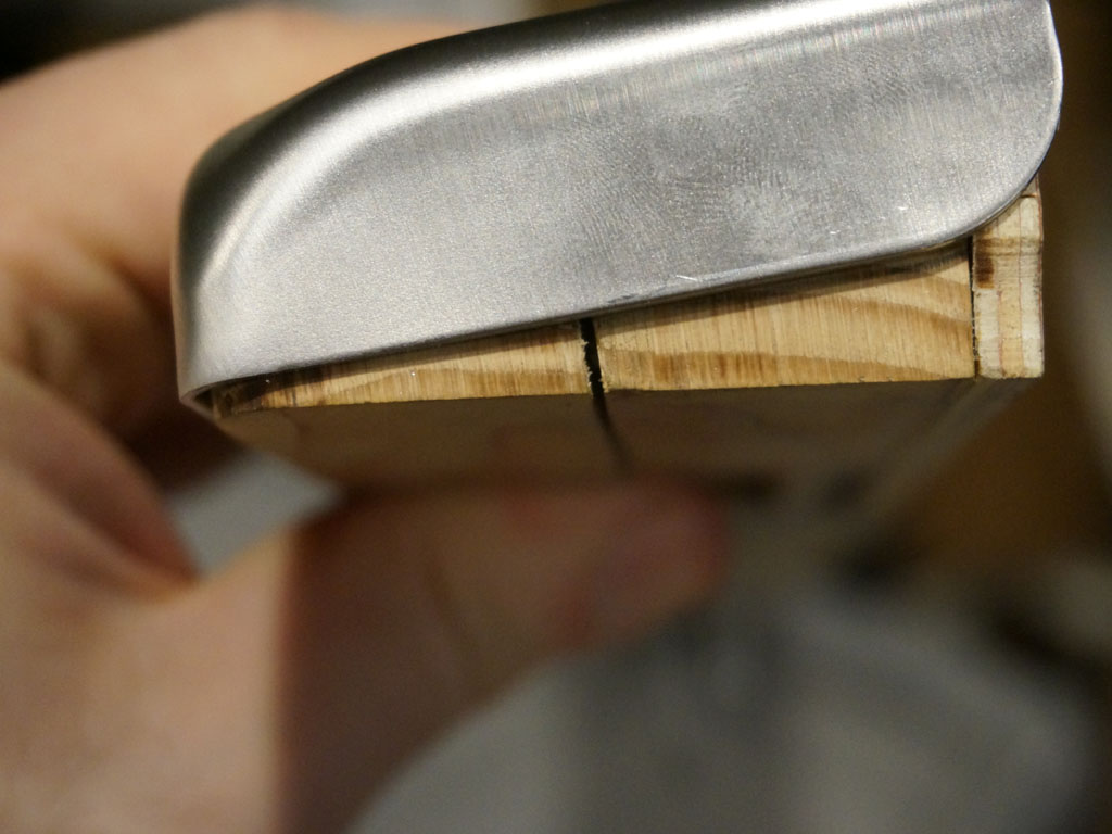
This flushed the bottom up nice and flat.
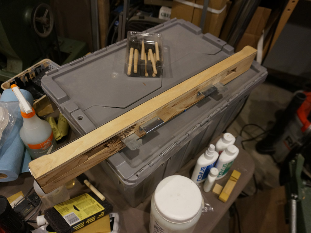
I floated the hobby ply caps on top of wood glue; this covers the backs of the pins and builds up the thickness.
But then I looked at that and thought, man, I better put a clamp on that.
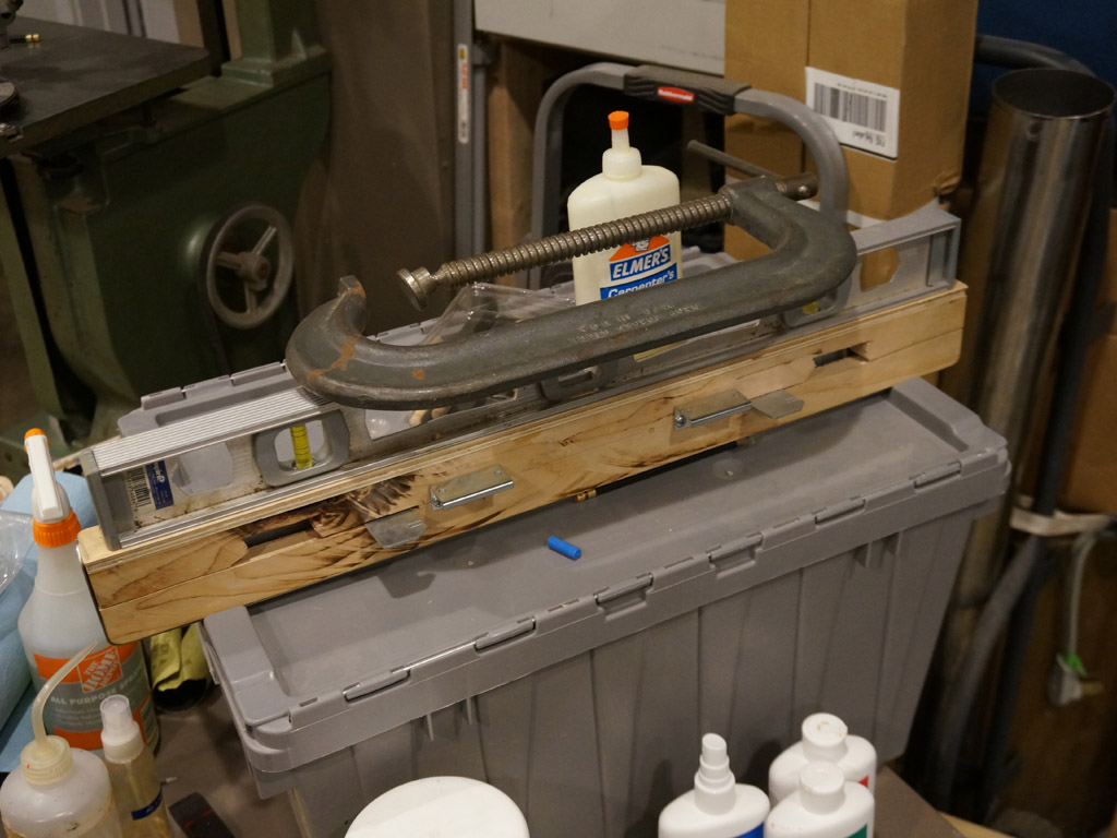
DONE.
While the glue dries, let's get started on those 25mm linear bearing rails.
The aluminum extrusion bridges over one of my assembly screws, and that is unfortunate. But that part isn't
particularly load bearing in my opinion - so a clearance cutaway will work nicely.
About this much should go.
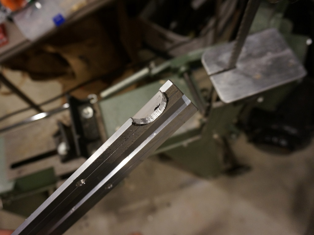
Rough it out on the bandsaw...
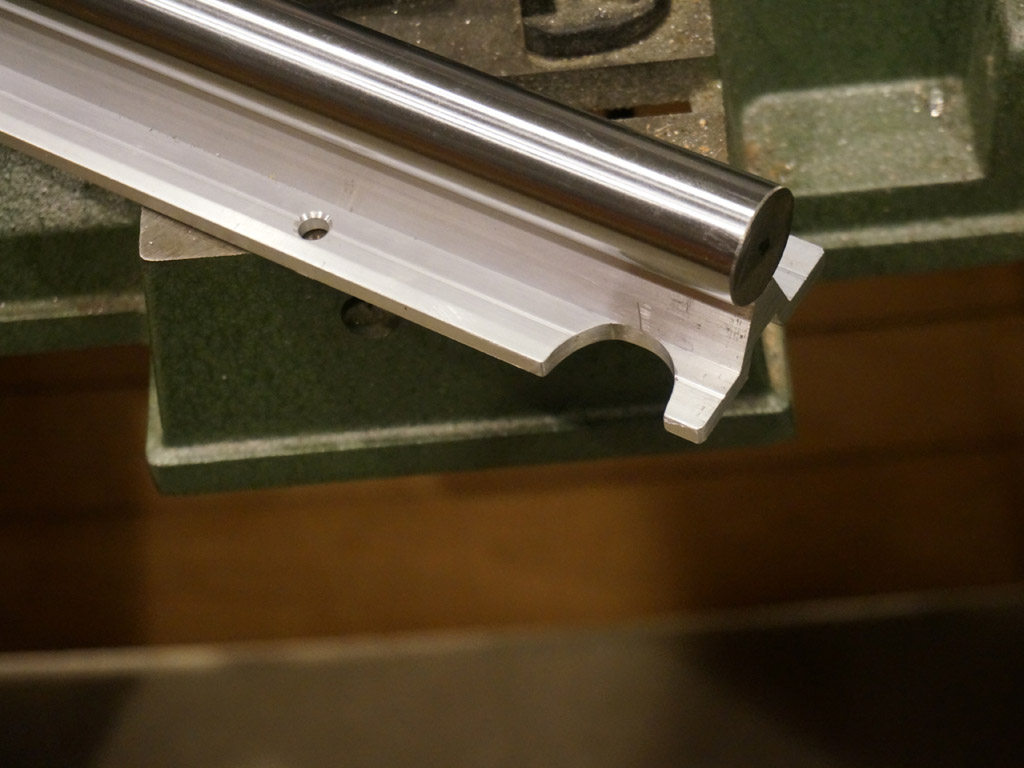
Polish it out with a dremel sandpaper drum...
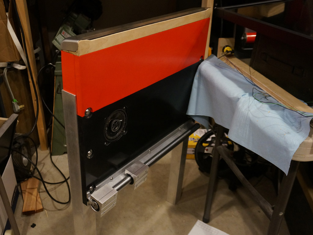
and it mounts up like so.
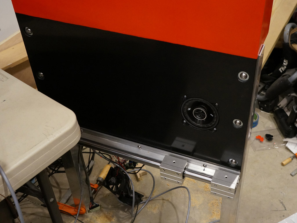
The front rail wasn't too hard - there's not much delicate electronics in the way, and, you can't see the backside
of the attachment points very easily.
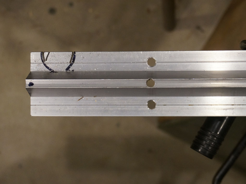
The rear cabinet is a different story. That required disassembly and careful drilling in from both ends.
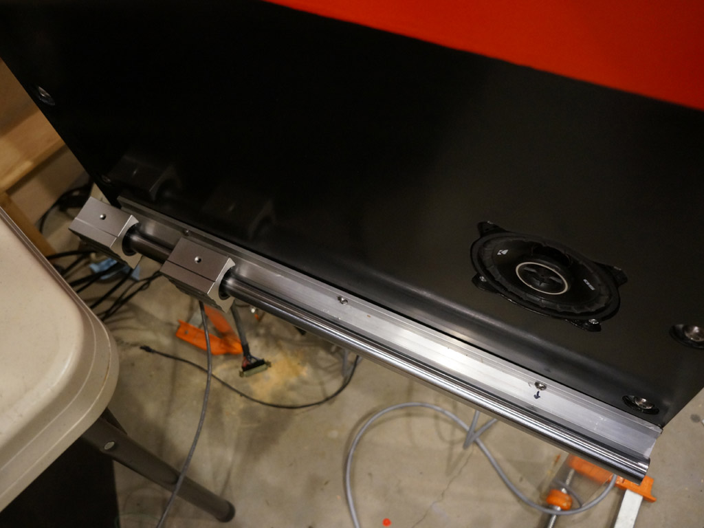
A surprise - the rail reveals my cabinetry is cupped. Touching on the ends, there's a gap of a little under a quarter inch in the center.
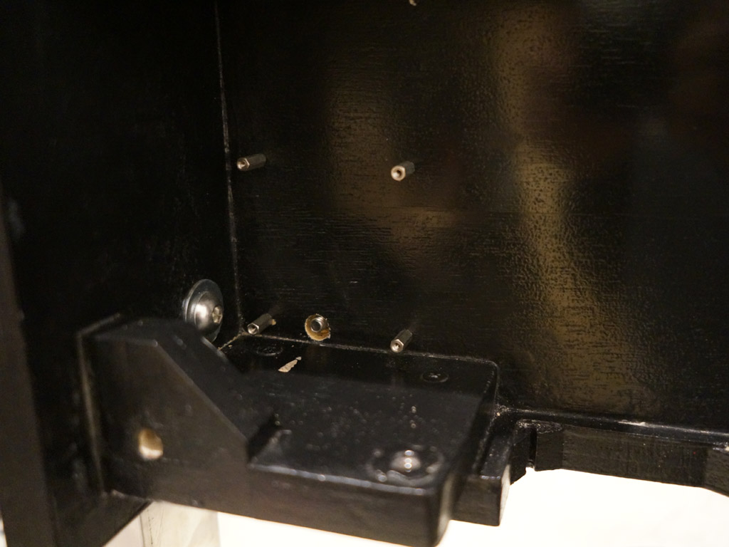
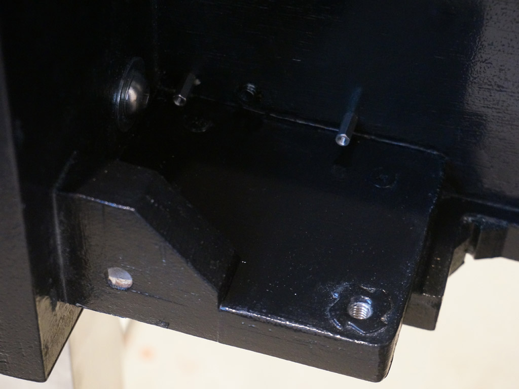
Obviously, the circuit board had to come back off the standoffs here.
The drill nicked the paint below the bolt hole, that'll need touched up.
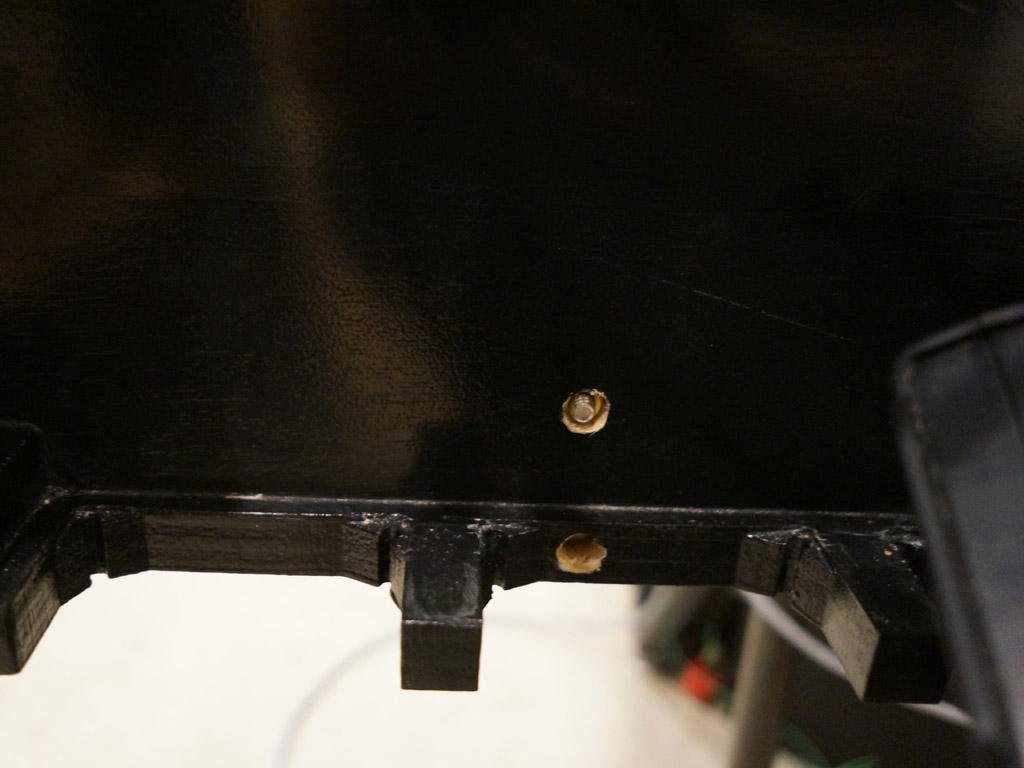
In the center, you can see that the lower screw centers within the fan web - that will be hidden by the center fan.
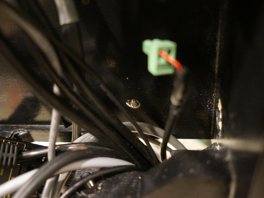
On the right, the screws go under the power relay. The hardware is sub flush, so the relay will fit back over it.
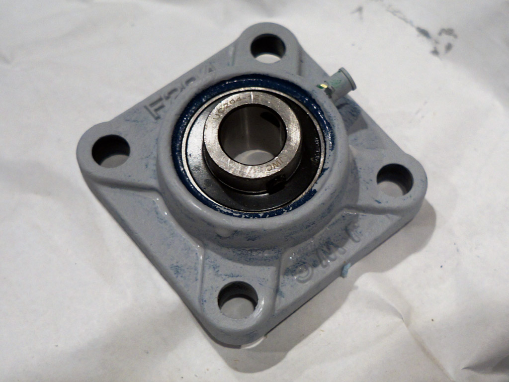
I was initially going to machine compound 3' flanged bushings to mount the axle that the playfield will turn about, but
then I found a cheap deal on some spherical bearings in pillow blocks that will suit my purposes aside from one detail.
From the factory, they are dark blue.
That will not do.
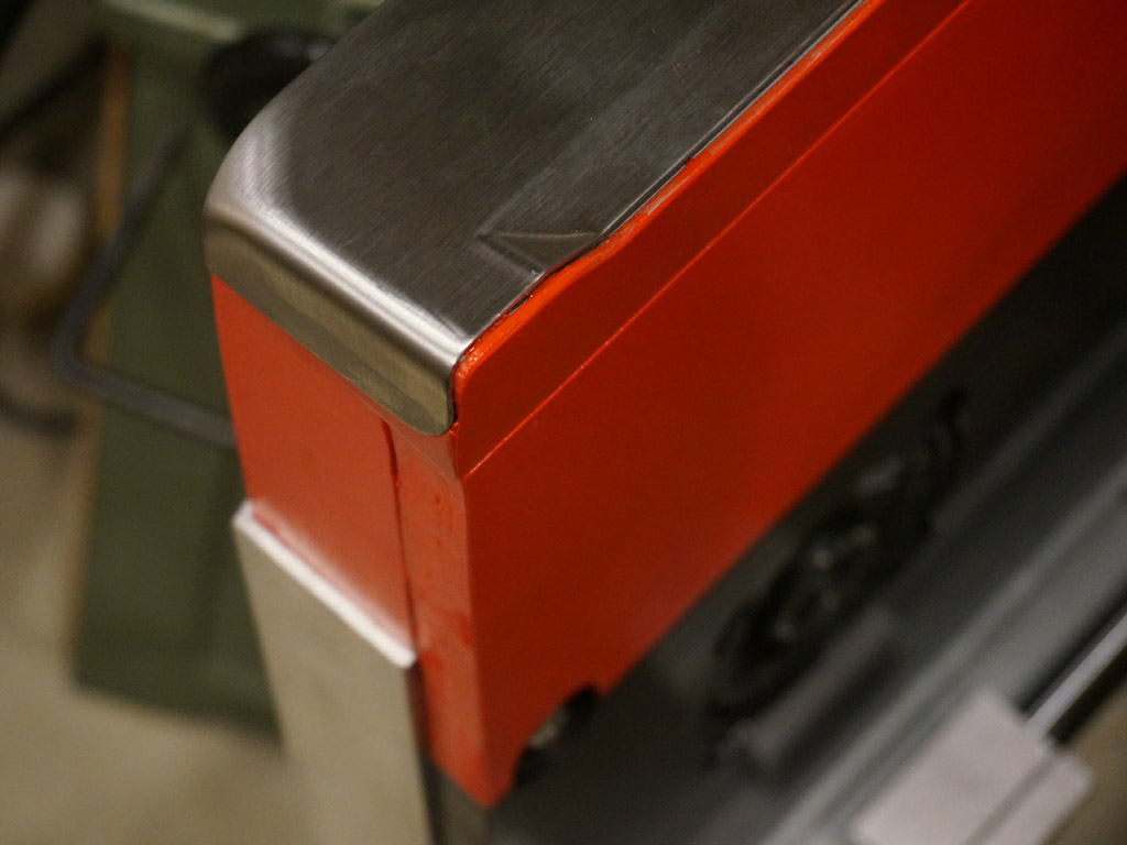
While I had the primer out, I also figured it was time to do the final work on the lockdown bar assembly.
A bit of plastiwood filler and matching the shape of the metal produces a contour like this.
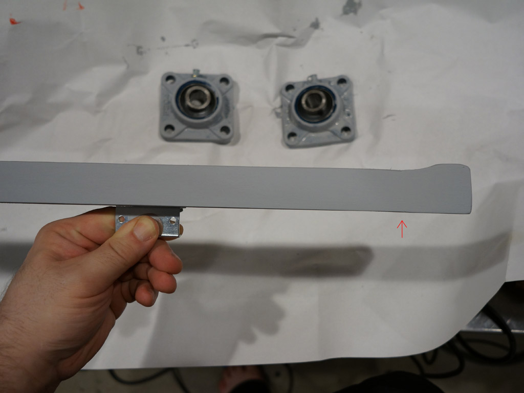
I'm getting better at hiding seams - the red arrow shows where the two pieces of hobby plywood meet. That almost wasn't even a fight!
Black touchup to fix where the drill kissed the floor.
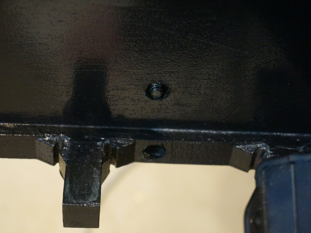
And a few dabs into the other holes as well makes it look much more intentional.
Back on the front side of the rear cabinet...
I spent a while looking at and thinking about the gap I had in the center of the 25mm linear rail due to the cabinetry cup.
I wondered what the relative stiffness was, between that roughly inch sized hardened steel rod and the 3/4" plywood structure.
I tried setting my camera up on a tripod, looking down at it, and recording video, then tightening all the screws down to pull the gap out.
Reviewed the video. It didn't look like the rail flexed. It looked like the plywood flexed.
Hmm.
I set up a ridiculous lashup to set the dial indicator I use on my lathe and mill to reference on the center of the rail, and then
very carefully worked the screws back and forth, from slacked out to totally tight with the gap pulled flush.
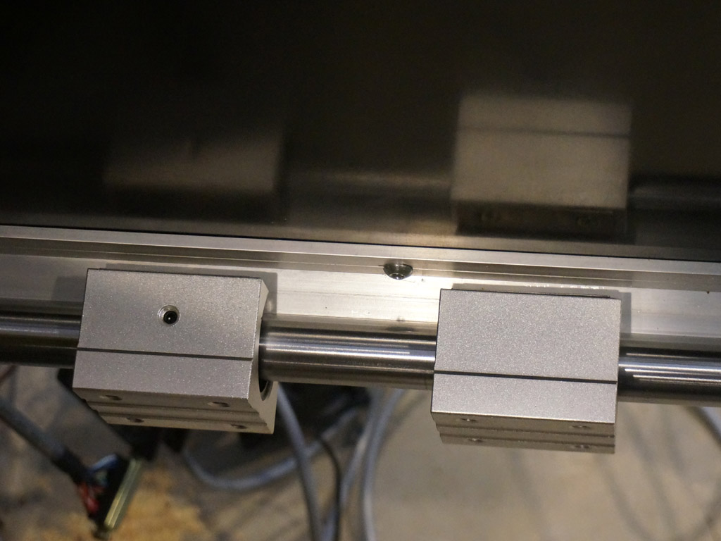
Conclusion: Under full screw tension, at the center, the plywood structure pulls about 0.2" out, and the rail pulls about 0.006" in.
I think I can live with six thou of possible curve over a 24" long run. I think that's as nothing. So heck with building spacers to go under it - I'm just going to crank it down and let the steel bar be the truss that straightens out the wooden box here. I'll revisit that if the control panel balks moving across it, but given the panel is going to be a wooden structure about 42" long between the rails, I think it's fine.
Next: More red paint.
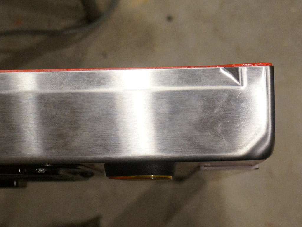
First coats of red on the lockdown bar assembly.
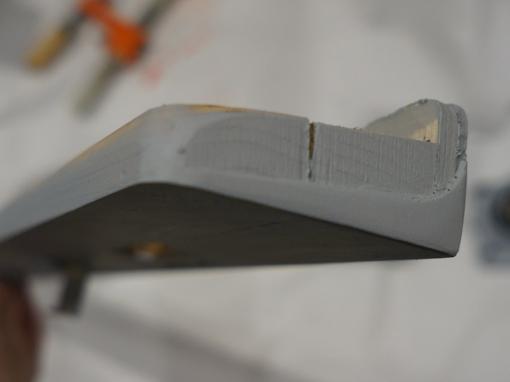
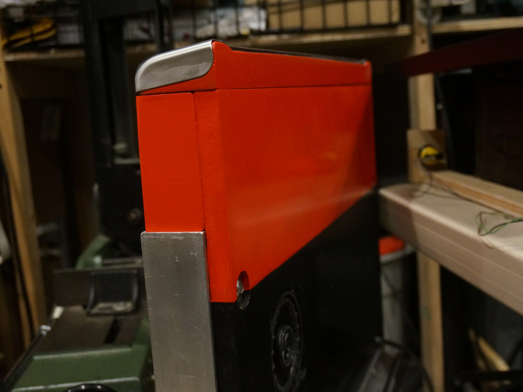
I feel a need for another small detail like the red stripes on the rear hatch arises here. Looking down on the profile of
the lockdown bar, you can see the red part matches the front-back depth of the front cabinet, which is slightly deeper than the lockdown bar is...
This means it sticks out the back a bit. Looking down on it from the pinball player perspective, that red is far too conspicuous -
that's going to show a lot in the necessary gap between the lockdown bar and the pinball playfield.
(Some gap has absolutely got to be present for the rotation of the playfield to clear the front cabinet.)
I plan to fix this by painting the top edge - basically, the whole part you can see red in the above picture - black.
That shouldn't look bad from the side when you are in the cockpit, and should fix the problem when looking down at it as a pinball player.
First coat of red paint on the bearing blocks:
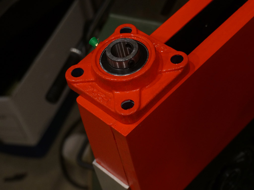
Needs a few more coats, but that's gonna look good as a match.
It turns out the bearing blocks land wholly within the red areas of the cabinets front and back, so, no fiddly black two tone needed.
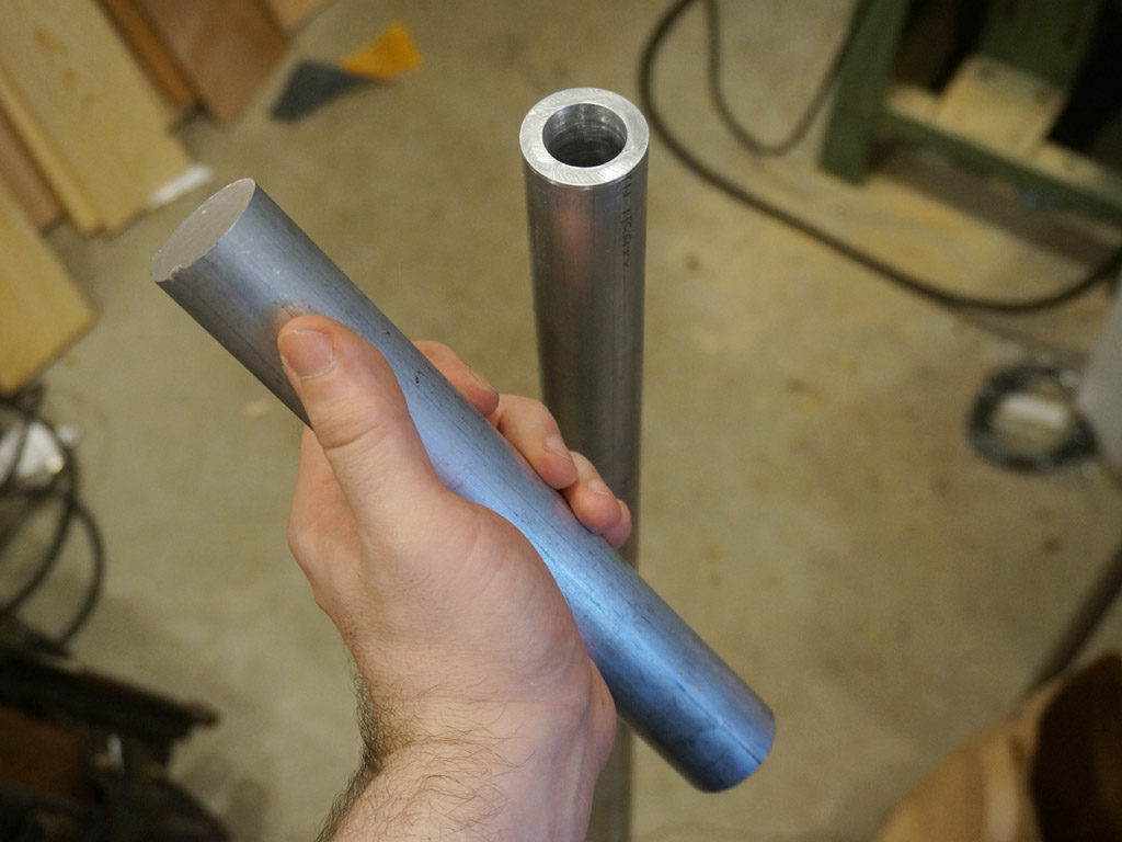
I got my hands on the materials I'm going to be constructing the playfield axle from.
1.5" OD, 1" ID, 0.25" wall thickness 6061 aluminum tubing will be the spine of the axle,
with lathe turned endcaps made out of 1.5" solid round stock.
The axle endcaps will be a 3/4" pin for the bearing, a full diameter flange, and a 1" pin for the inside of the axle tube.
Well, I lied, it's actually 0.748" and 0.982" respectively.
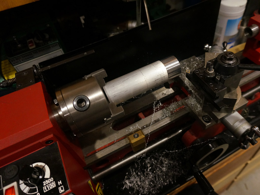
Making shavings.
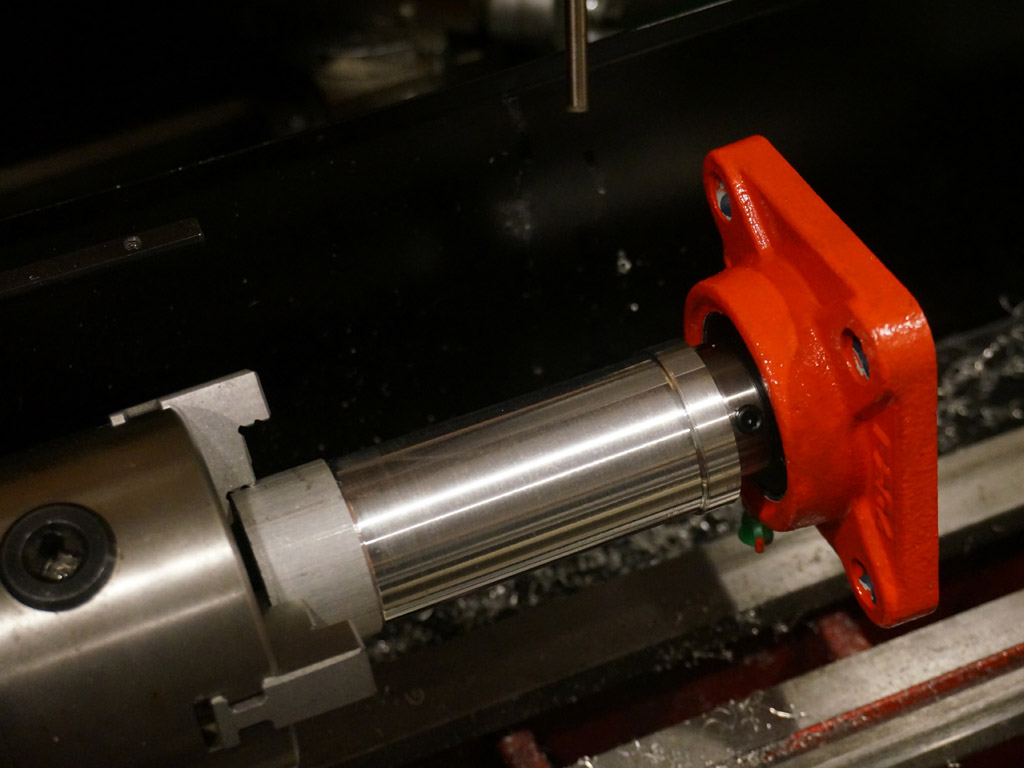
Got the first pillow block to be a tight slip fit. The bearings have two setscrews to lock onto the shaft.
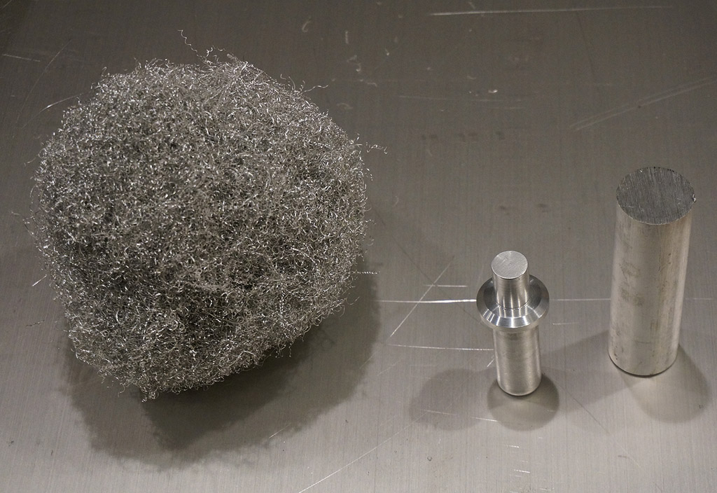
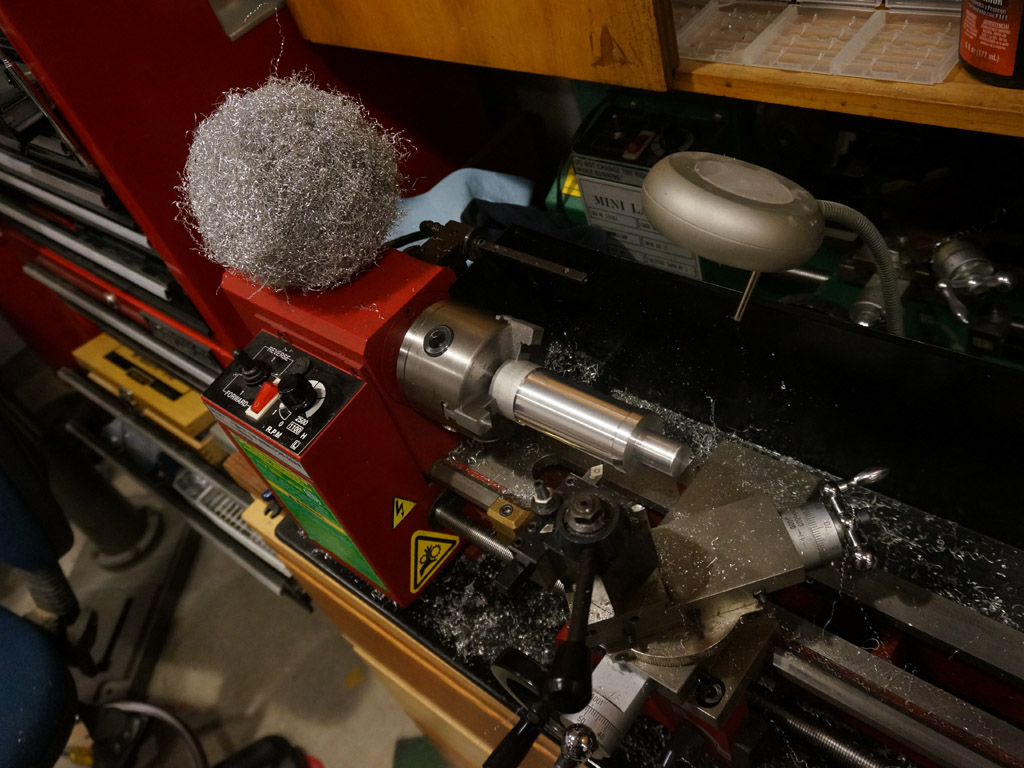
Here's the blank I start with, one finished cap, and the approximate amount of shavings you remove to make it happen.
Getting the second blank to run true in the chuck...
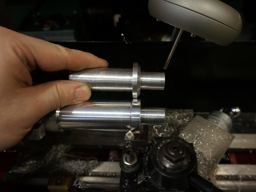
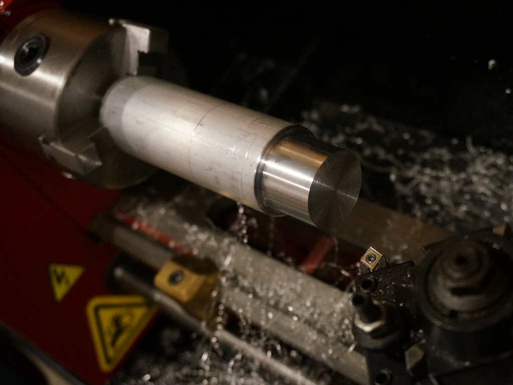
I went for a 0.3" deep flange of full diameter with a chamfer to look fancy.
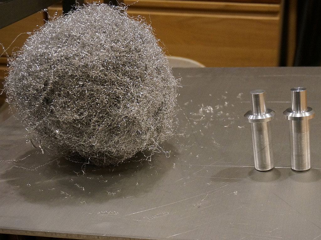
Reasonably matched pair of end caps and a lot of shavings.
As installed, they go like so:
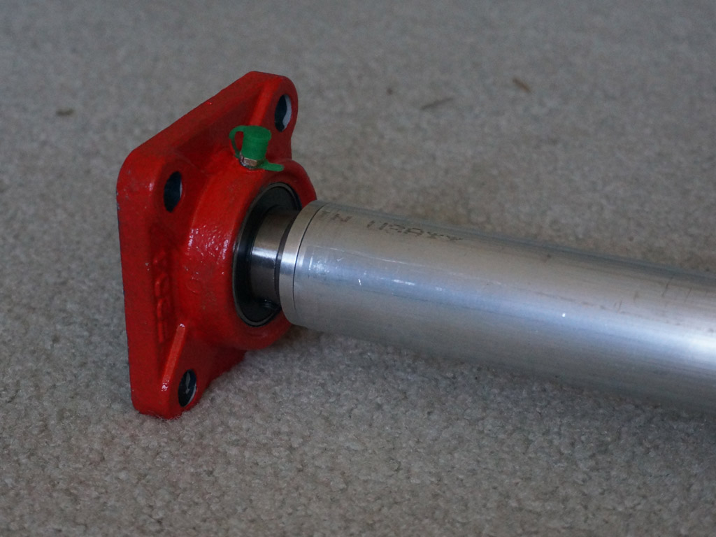
Technically the flanges aren't necessary, and the parts would have been a whole lot easier
to fabricate without them - but they're classy.
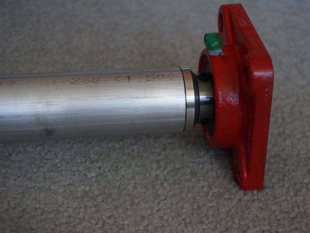
I mean, that's a good looking flange. They also guarantee the face up against the bearing core is square and true
even though I can't turn the entire axle in my tiny little lathe to square the tube ends to a precision surface.
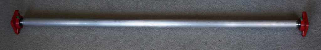
The complete axle core.
Continue