This is the log of building Shapeshifter - a one-off machine that is somehow both a full size vpin cabinet...
and also a sim-pit cockpit for flight simulators, racing games, and most of the sit-down arcade games.
(It's ambitious, but, I've already completed Mimic, so I think I may be able to do it.)
Previously...
My design doesn't have a hinged backbox like a real pinball table.
There's also an LCD panel going right through the center of the hinge region. They will fold once, but they don't unfold very well.
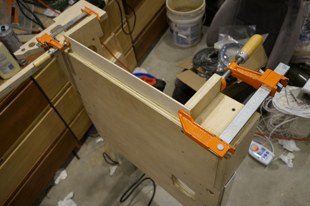
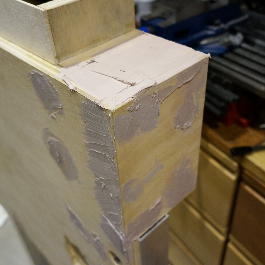
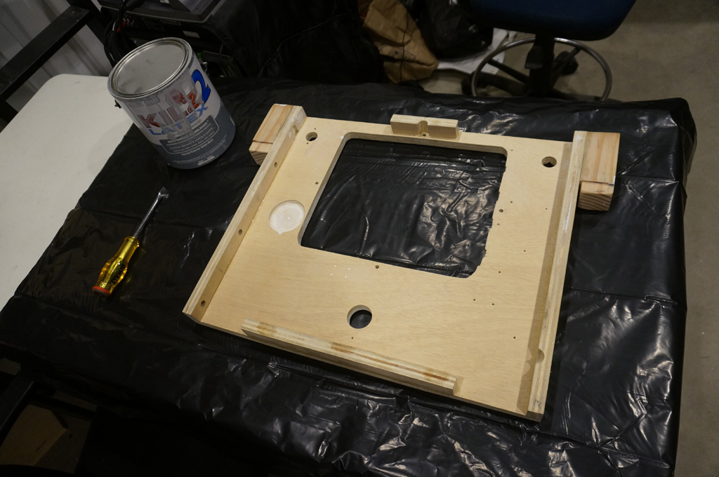
I still wanted a neck to visually separate the backbox a bit, though. Reducing the thickness of the front plywood was the best available trick. Here's the thin panel going in.
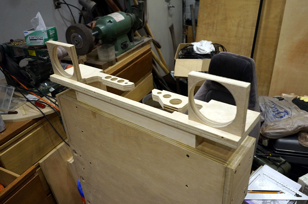
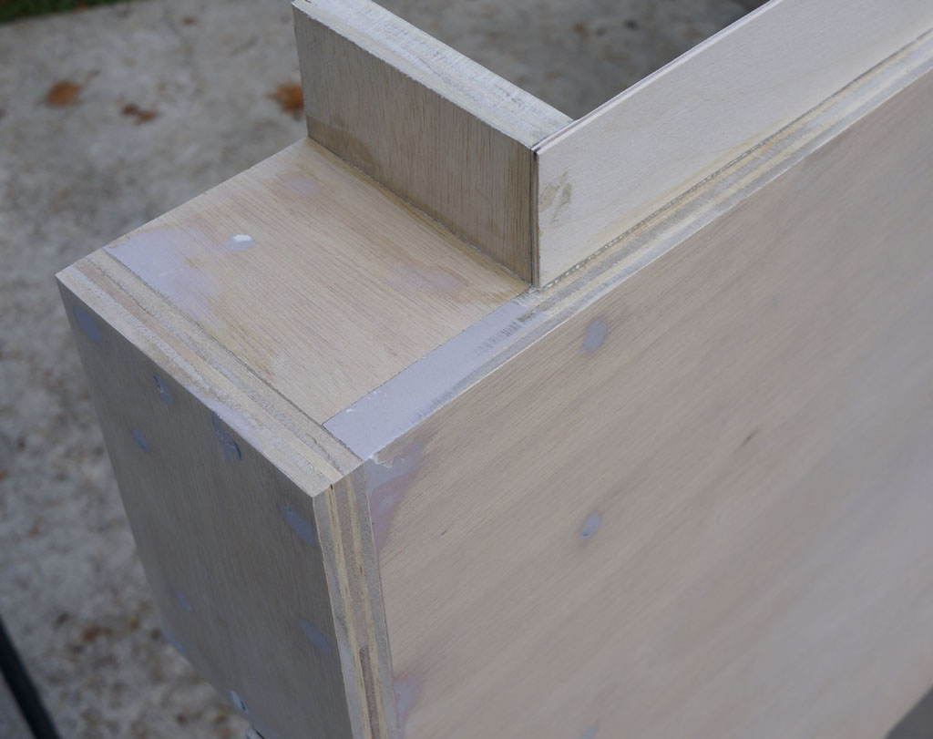
The backbox floor sits on top of the neck. The backbox speaker mounts go into the corners of it, like so - they taper down to almost nothing, but there's not a lot of room in the planned backbox and there
shouldn't be much load on that inside top corner anyway. The upper backglass panel will sit on top of these, and the DMD panel will slide up through the neck, between the speakers.
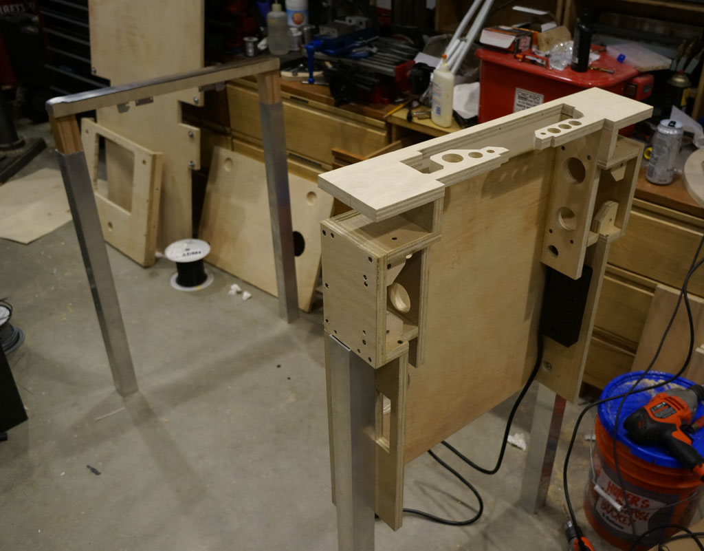
Here's the structure from the back. All this in back is now glued and screwed together, with the exception of the legs, which are removable for painting the thing.
As you can see from the cheek above the rear leg... sometimes, there are a lot of screws. I'll be bondoing over all those screwheads during the prime and paint process, though.
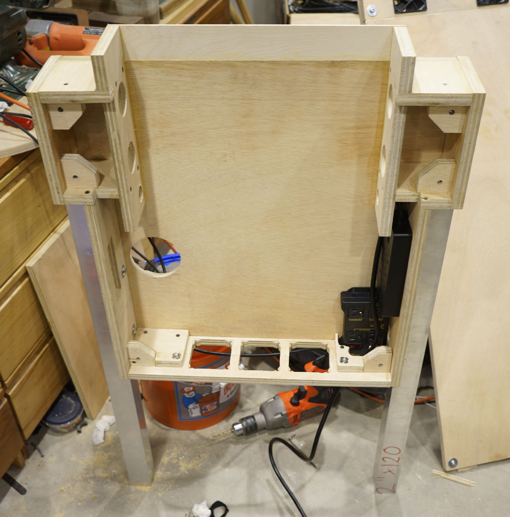
This is the floor of the backbox cabinet going in. It's two pieces, the inner one is glued and screwed, the outer one remains removable
via the two button screws going up from below into the two T nuts you can see, so it can be pulled off to swap out the intake fans when necessary.
The inletting clears the power relay in the lower right corner flushed to the outside, which is the main 120v AC line in receptacle to power the whole machine.
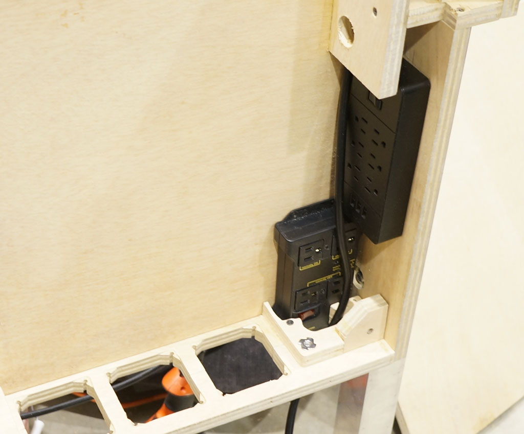
I found a 3x2 arranged power strip that clears the 3/4" hatch setback to mount on the wall above the power relay.
This will drive the DMD monitor, backglass monitor, playfield monitor,
stereo amplifier, steering wheel force feedback motor, and 12v actuator motor power supply.
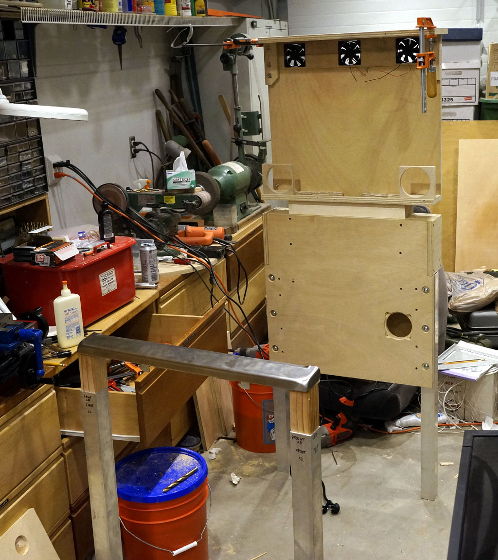
I couldn't resist attaching the rear hatch temporarily, because it carries the backbox roof, and gives a preview of the total sillouette
and size of the thing. It is kind of huge, but so are real pinball machines. Standing at the lockdown bar, it feels about right.
With the completion of the front legs, all four legs are now done.
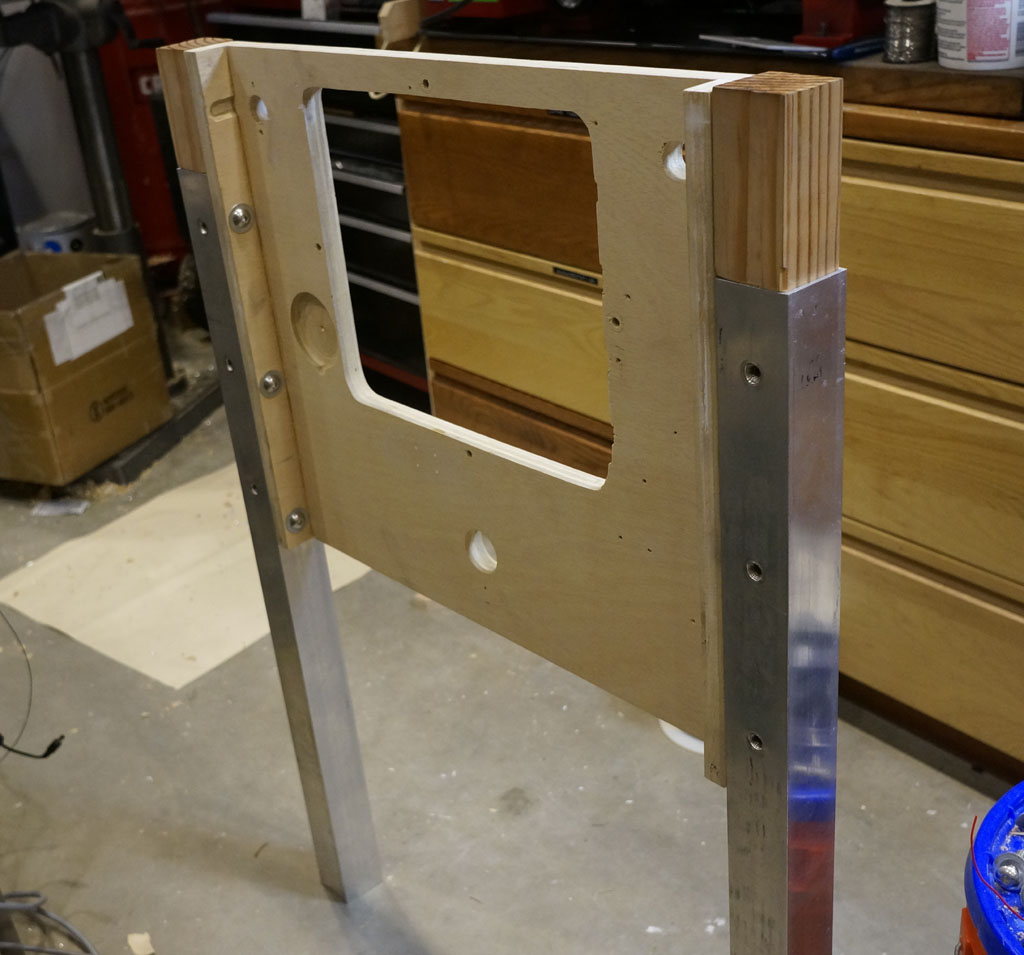
The spacing of the inner leg-attaching button screws is set so that, once this box is sealed up, the upper two can
be reached through the open coin door, and the bottom one can be accessed through gaps in the partial floor
(which is still to be built). However, after playing with it a bit, I think these six inside the front cabinet
would be easier removed via a ratchet and socket, so I'm going to flip these over to normal hex head
bolts. (The other 18 leg attachments will stay button head.)
Moving to the back cabinet...
I've been confirming and fine tuning the layout of parts. This is roughly the current idea for the back lower cabinet:
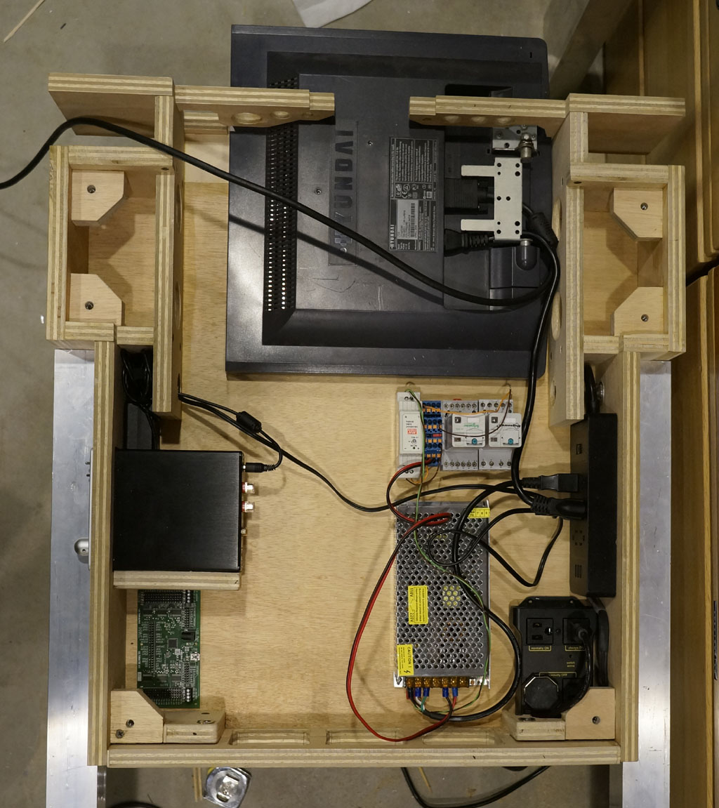
The DMD panel looks off center, but that's an illusion caused by the unused speaker area formerly below the
display, but now beside it. The display glass is centered in the neck, and that's also the defining reason for the neck's total width.
The amplifier power brick is above the amp, tucked off on the left. The amp is up on a shelf, which means you can't
see the driving-mode speaker directly behind it. Below that is the Ultimark IPAC Ultimate-IO that will
be the main computer interface brains of the thing, which I'm giving fairly prime real estate here to ease future
diagnostics and servicing at the header pins.
On the right side, from top down, there's a chunk of DIN rail housing several relays and a breakout box.
Then, a 3x2 power strip, a 12v power supply (to run fans, linear actuators and solenoids) and the
USB-controlled power relay, which is also the main power in.
The unused area in the center is a wind tunnel to get airflow from the bottom-mounted intakes, behind the DMD panel
in the neck, and up into the upper backbox. The entire PC will live elsewhere (just in front of the rear legs) and there's also
going to be a few other large project boxes elsewhere to house other guts - so this is by design only a portion of the internals.
This weekend was, however, mostly about bodywork. So much bodywork.
The bondo goes on.
And lo, it is ugly.
The bondo comes off.
I am not good enough at this to nail it in one. So, at this point I can see everything I've failed to fill sufficiently, and coat two goes on.
While I'm a big fan of the strength of the cured bondo, my technique with it leaves much to be desired, and it's
a much bigger hassle to work with. By the third pass, I flipped over to using jointing compound instead.
More filler goes on.
At least this stuff is easier to apply - less bubblegum, more cake frosting.
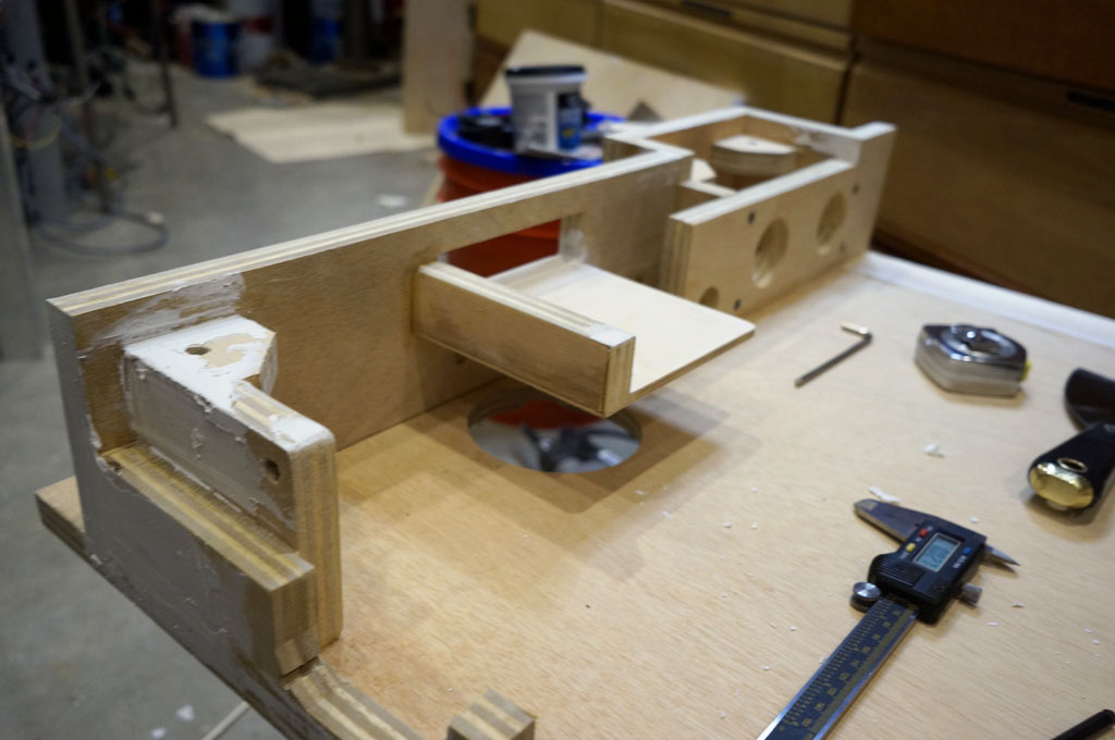
This picture of filler going on the bottom also nicely illustrates that shelf that the amp rides in, and how the speaker sits beneath it.
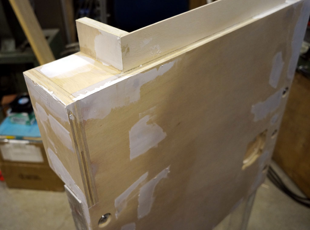
Behold, three layers of sanded fill.
This stage of power sanding had me looking like possessed King Theoden by the end of it, white beard and all.
But, I'm now mostly done with the bodywork on the back cabinet. I think. At least, until I put a layer of primer
on it and see all the sins that still remain, at which point it's probably back to more filler again.
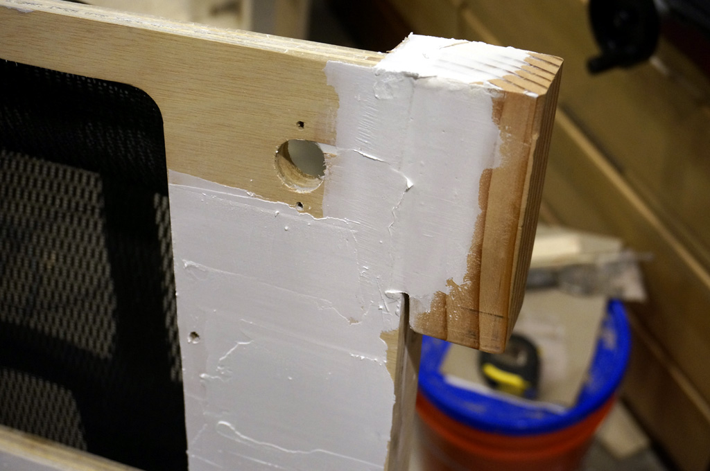
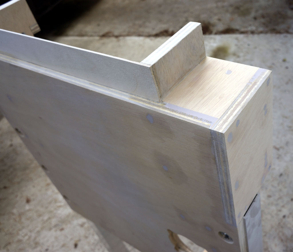
Corner blocks glued onto the front cabinet. And more fill. always more fill.
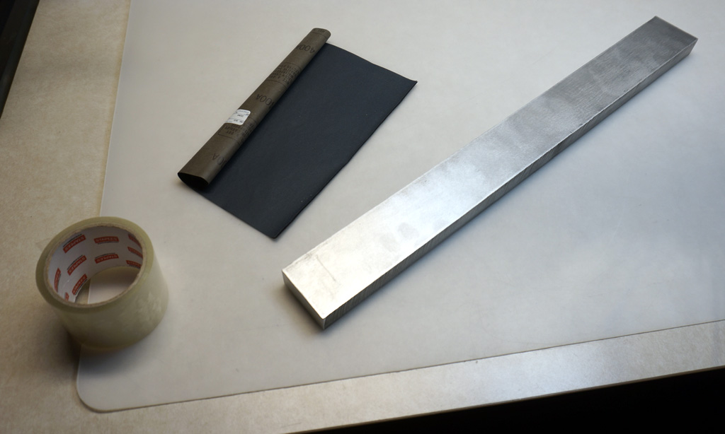
I want these corners to blend in like the whole front cabinet is one piece, so I made myself a two foot longboard out of some aluminum bar I had laying around.
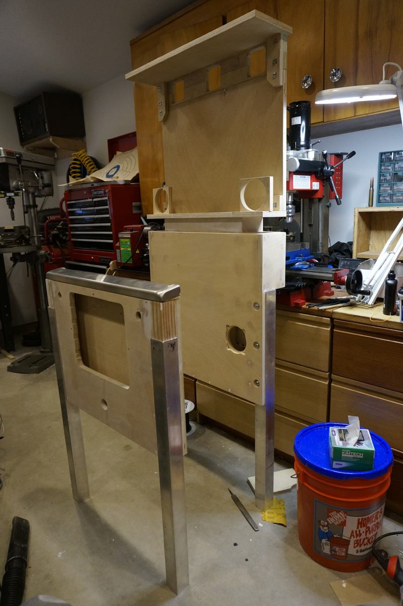
Front cabinet next to back cabinet in mock assembly.
Looks like I'm making the shortest pinball machine EVER.
It's priming time. At least for the parts of the thing I won't be able to reach once assembled.
Continue...